
VIADUCT OVER THE VICARIO RAVINE (GRANADA)
technical specifications
Location
A-44 Motorway (Granada)
Scope of Works
Detailed design
Structural type
Composite continuous girder, with constant depth
Construction process
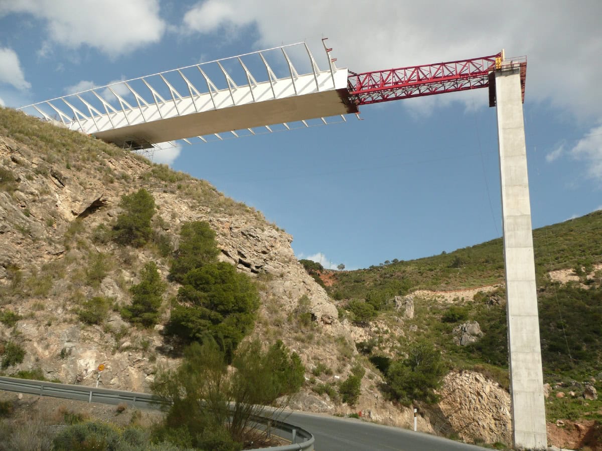
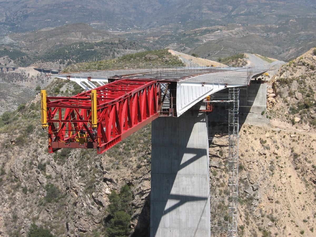
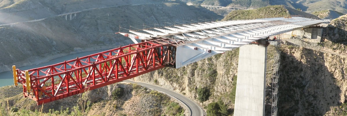
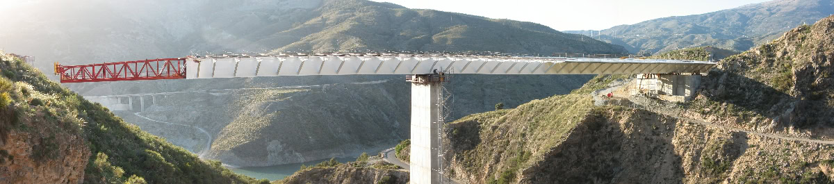
Incremental launching construction, using launching nose 28 m long
Overall length
175,0 m
Spans
2x87,5 m
Deck width
24,0 m
Deck maximum height
70,0 m
Project Description
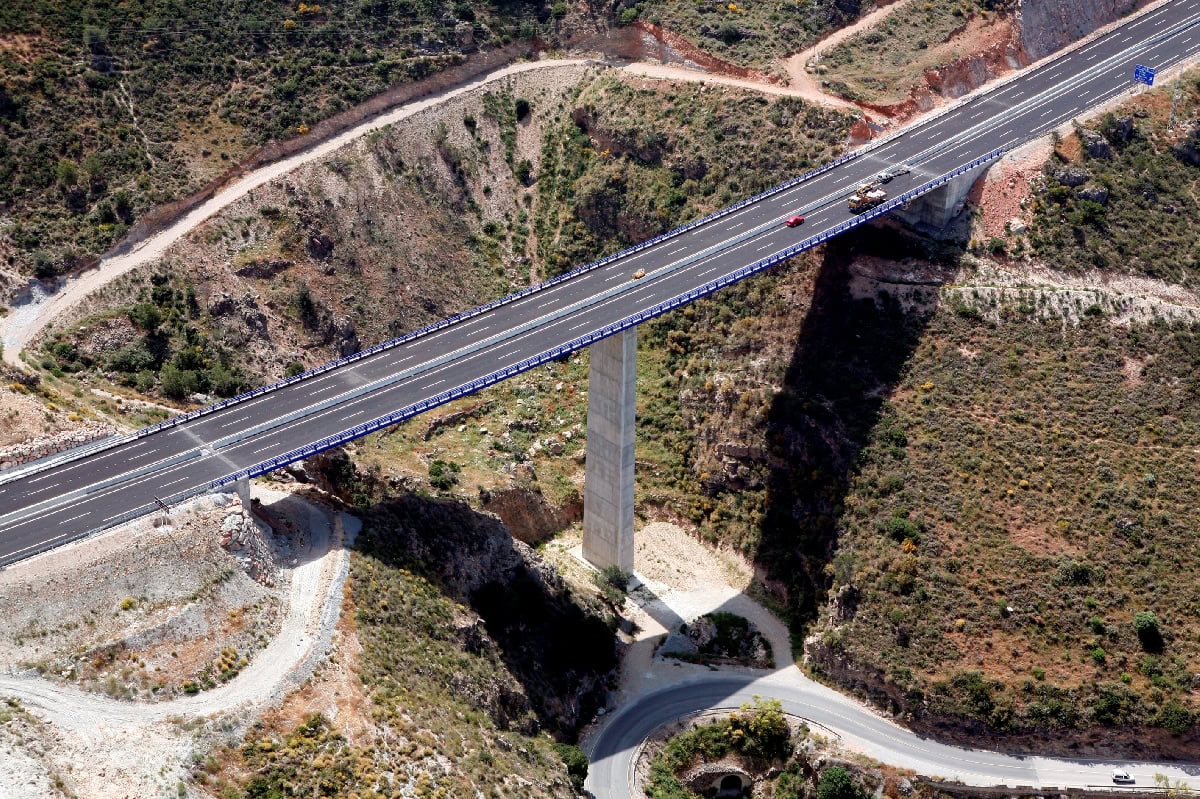
The Vicario Viaduct is located in the Izbor-Velez section of the A-44 motorway when it crosses over the Hornos Ravine, also known as the Vicario Ravine, near the Rules Reservoir, in Granada.
The location needed a 175 m long structure to cross the ravine. The slopes of the adjacent hillsides are quite steep, so it wasn´t possible to build support piers on them. Hence the final structure consists of a two span bridge each span being 87,5 m long.
The deck, which is 24 m wide, carries the complete dual carriageway.
The structure is a continuous girder of 175 m in length and 2 spans 87,5 m long. The depth of the deck is constant at 4,52 m (4,20 m the steel structure, and 0,32 m the concrete top slab).
The cross section is an 8,0 m wide and 4,20 m deep steel box. There are cross truss transverse diaphragms every 4,375 m and inclined struts, which support the transverse cantilevers. These cantilevers are 8 m long and complete the total section up to 24 m.
The steel box is completed with a concrete top slab 0,32 m thick. The steel used is S-355-J2G3 for the plates and main structure and S-275-J2G3 for the laminated steel profiles.
The concrete used for the deck is lightweight HA-30.
In this area a seismic design is needed. Transverse seismic loads are resisted by the piers and abutments. Reaction blocks at the abutments were provided to correctly resist the effect of longitudinal seismic loads and restrict longitudinal movement.
A steel deck was built behind the E1 abutment, and it was launched into its final position, with a steel launching nose, 27,5 m long. The maximum deflection during the process was 1500 mm.
The key aspects during the launching process were the curved horizontal alignment, the deflection at the nose during the maximum cantilever stage, the large reactions forces on the bearings and the transmission of these concentrated loads to the webs (patch loading).