
RIQUIANEZ VIADUCT (LAS PALMAS DE GRAN CANARIA)
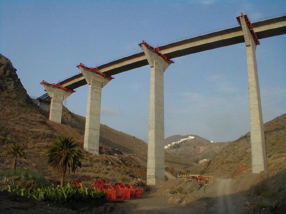
- Location: GC-3 Highway (Las Palmas de Gran Canaria) SEE MAP
- Scope of Works: Detailed design
- Structural type: Prestressed concrete continuous girder
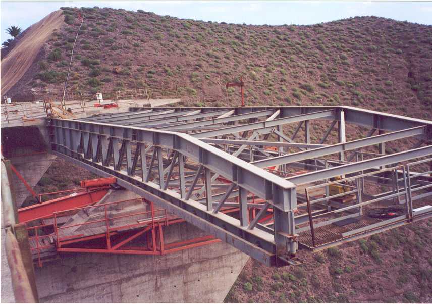
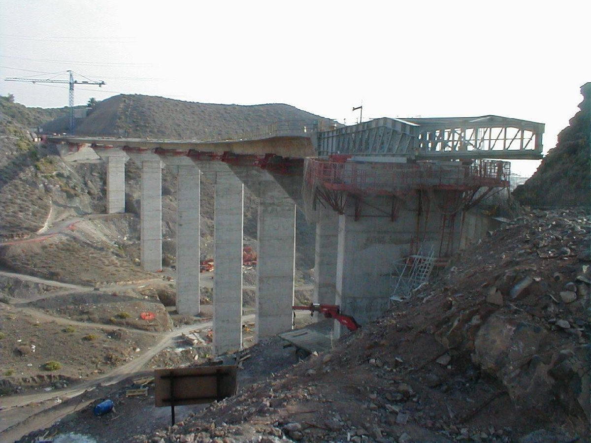
- Construction process: Incremental launching construction, using a steel launching nose
- Overall length: 313,15 m (left) and 350,10 m (right)
- Spans: 37,95+5 x 47,45+37,95 m (left) and 36,85+6 x 46,06+36,85 (right)
- Deck width: 14,0 m
- Deck maximum height: 70,0 m
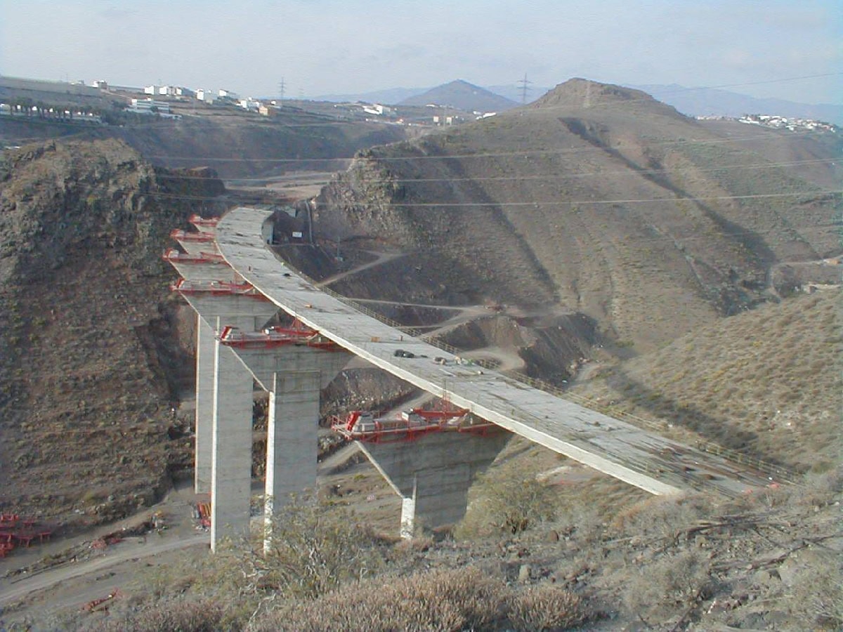
The Riquianez Viaduct is located on the Las Palmas de Gran Canaria Ring Road in the “Picoviento-Jinamar” section. The viaduct crosses over the Riquianez Ravine.
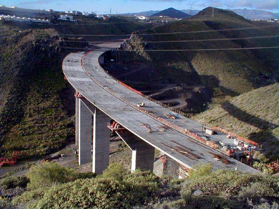
The structure is made of two twin girders, 14,0 m wide. The platform is made up of three 3,5 m lanes, a 1,50 m wide right hard shoulder, a 1,20 m wide left hard shoulder and the lateral barriers.
The horizontal alignment is a circular curve of 498 m radius. The vertical alignment is a concave curve with a parameter of kv=12000. The cross slope is constant at 8%.
The most suitable cross section chosen for the deck was a prestressed concrete box section with a constant depth of 2,60 m and span lengths of:
– 37,95+5 x 47,45+37,95 left deck (overall length 313,15 m)
– 36,85+6 x 46,06+36,85 right deck (overall length 350,10 m)
The webs are 0,40 m thick, and both top and bottom slabs are 0,25 m thick. The top slab is also made up of with two lateral cantilevers, 3,20 m long. The thickness of the transverse cantilevers varies from 0,17 to 0,50 m.
The structures were built as an incremental launching construction, using a steel launching nose.
There is only one column for each pier. The piers support both decks with a trapezoidal shaped pier cap on its top section. The final pier of the longer bridge (right) is different, because it only supports one single deck. This final pier is in alignment with the abutment of the left deck. The height of the piers varies from 31,3 m to 67,3 m. The section of the piers is a rectangular hollow section with 0,35 m thick walls. Shallow foundations were used for all piers except pier P5 where micropiles were used.
Both abutments are a conventional system of stemwall and wingwalls, made of reinforced concrete, with shallow foundations. All bearings were POT sliding bearings.