
Bridges and Viaducts · Continuous or Beam
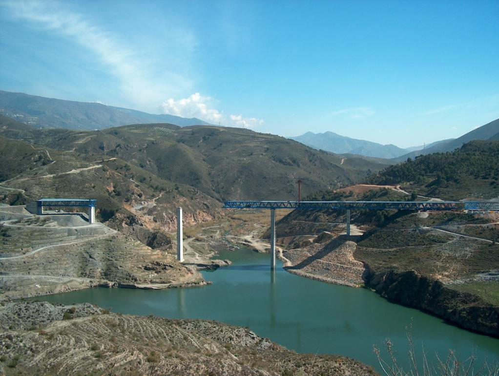
Guadalfeo Viaduct Over The Rules Reservoir (Granada)
technical specifications
Location
A-44 Motorway (Granada)
Scope of Works
Preliminary design, Detailed design, Technical Assistance during the constructions work
Structural type
Steel truss
Construction process
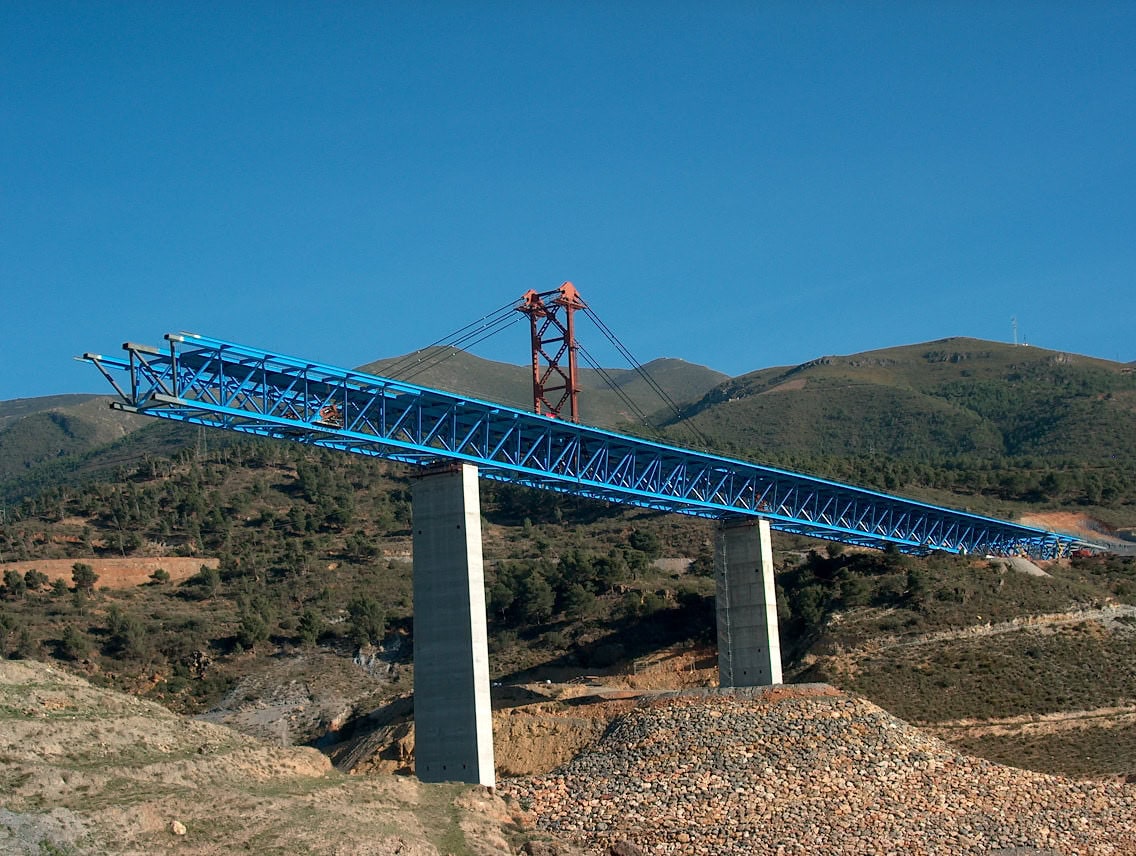
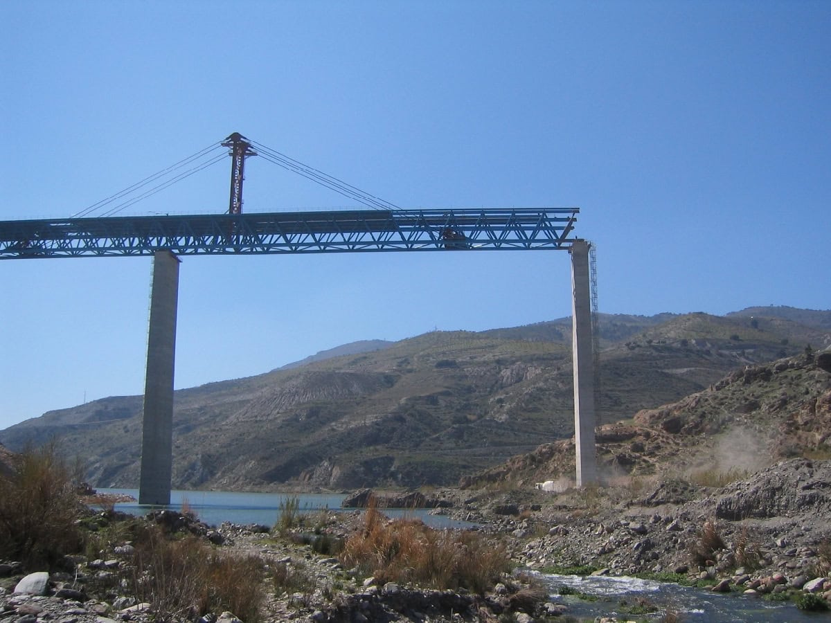
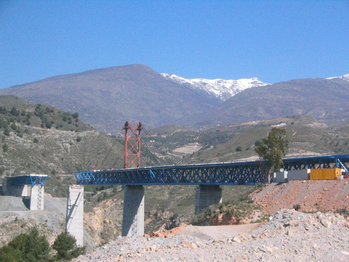
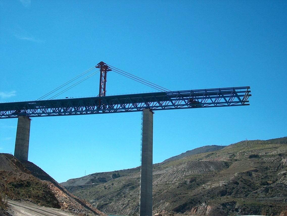
Launched bridge using temporary cables
Overall length
585,0 m
Spans
85,0+140,0+140,0+110,0+110,0 m
Deck width
24,0
Deck maximum height
100,0 m
Project Description
The Guadalfeo Viaducto is located on the Izbor-Velez section of the A-44 motorway when it crosses over the Rules reservoir.
The deck of the bridge is 24 m wide. The platform is a dual carriageway with two 3,5 m wide lanes in each direction; the outer hard shoulder is 2,5 m wide and the inner hard shoulder is 1,0 m wide.
The bridge is 585 m long; the horizontal alignment is a very gentle curve with a radius of 17200 m. There is a transition near the northern abutment. The cross slope is 8% near the northern abutment; due to the slightly curved horizontal alignment, the cross slope of the rest of the deck is 2%. With reference to the vertical profile nearly all the deck is on a slightly descending slope of 0,20 %. The maximum distance from the upper level of the deck to the ground is about 100 m.
The proposed bridge is a steel truss that is 9,55 m high; the platform of the deck is a 30 cm thick reinforced concrete slab. The total length of the bridge is 585 m, divided into 5 spans; the spans are 85+140+140+110+110 m long.
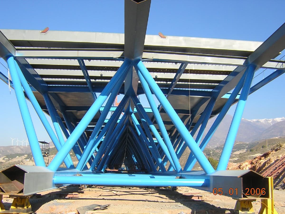
The cross section of the steel truss is 9,55 m deep. The truss is made of three main chords or beams on the upper level and another two lower main chords or beams. The horizontal distance between the main chords of the upper level is 9 m. The cross section of each beam of the upper level is made of five plates 1000 mm deep and 950 mm wide. It has a pentagonal shape to optimize the junction between the main beams, transverse and diagonal. The cross sections of the two main beams of the lower chord are similar to the beams of the upper level and are also separated by 9 m.
Groups of four diagonal bars are used to connect the main beams of the upper level to those of the lower level, with nodes distributed every 10 m. Each diagonal is a circular hollow section (CHS). Their diameter goes from 406 to 609 mm. Secondary beams are located parallel to the main beams of the upper level. A double T-shaped section 600 mm deep was proposed. The connection of these longitudinal beams to the main beams is made using transverse beams located every 10 m.
The piers are made of reinforced concrete. The cross section is a rectangular hollow section; measuring 4.5 x 12.0 m on the top of the pier. The transverse dimension of the pier varies from the top to the bottom of the pier reaching 16,5 m at the base of pier P5, which is the highest pier of the bridge (nearly 90 m high).
The lower part of the pier is made with a pyramidal shaped stand, constituting a transition from the pier itself to the pile cap that is 3 m deep. The foundations of piers P2 and P3 are made of 17 concrete piles 2 m in diameter, whereas the foundations of piers P1 and P4 are made using 14 piles 2 m in diameter. The piles cross a thick layer of alluvial deposits until the rock layer is reached.
The abutments are made of cast on-site reinforced concrete. Both abutments have a shallow foundation onto superficial layers of adequate resistance. Shock transmitter devices are connected from the deck to the abutments to correctly resist the effect of seismic loads.