
BRIDGE OVER THE OTA-GAWA RIVER FLOOD CONTROL CHANNEL HIROSHIMA
(JAPAN)
- Location: Hiroshima Bay (Japan) SEE MAP
- Scope of works: Preliminary Design (International competition – 3rd award)
- Structural type: Continuous extradosed girder with a diagrid web
- Construction process: Span by span construction using cranes on boats
- Overall length: 376,0 m
- Spans: 40,0+116,0+3×58,0+46,0 m
- Deck width: 19,25 m
- Deck maximum height: 20,0 m
This project was developed by TORROJA INGENIERIA and MPC ARCHITECTS for the International Design Contest promoted by the Municipality of Hong Kong in 2009. The object of the contest was the definition of the preliminary design of a new bridge over the Ota-Gawa flood control channel in Hiroshima when this channel goes into the Bay of Hiroshima.
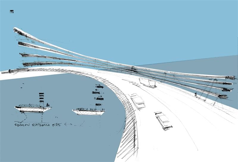
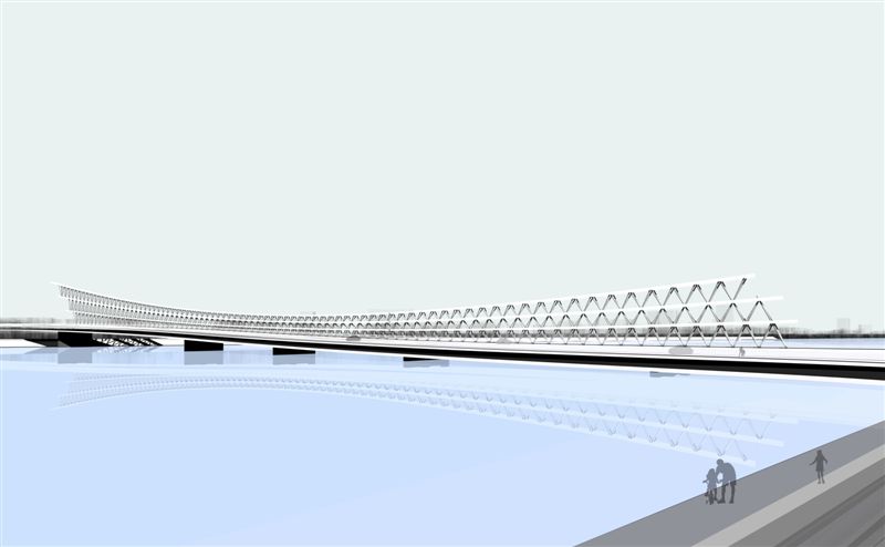
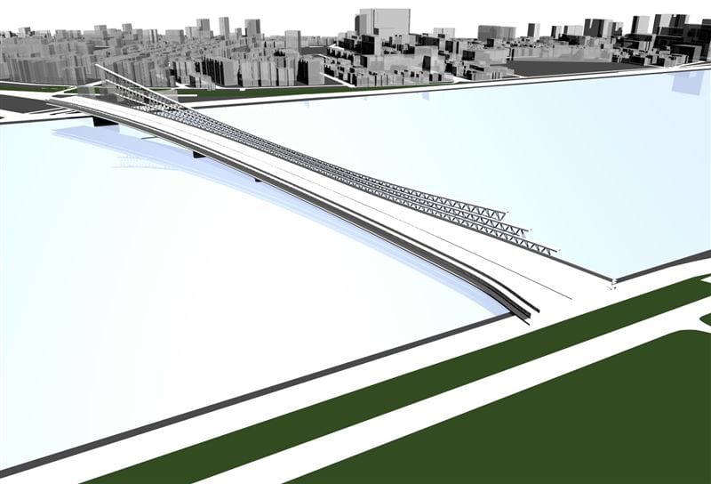
The proposed bridge is a continuous structure; the total length is 376,0 m divided into six spans 40,0+116,0+3×58,0+46,0 m. The main span is 116,0 and the depth of the deck is 2,5 m, so it is a very slender structure, with span-depth ratio equal to 46. The cross section of the deck is an L shape section. The horizontal bottom leg of the L section is the composite deck itself that is 19,25 m wide and 2,5 m deep.
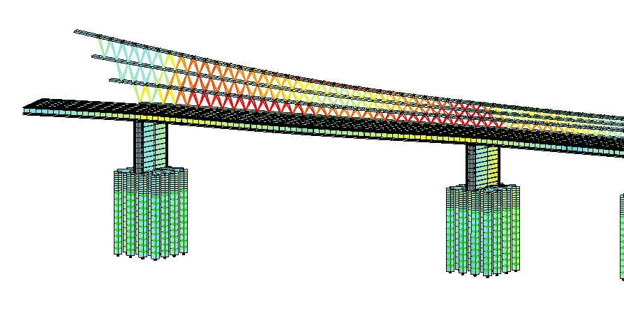
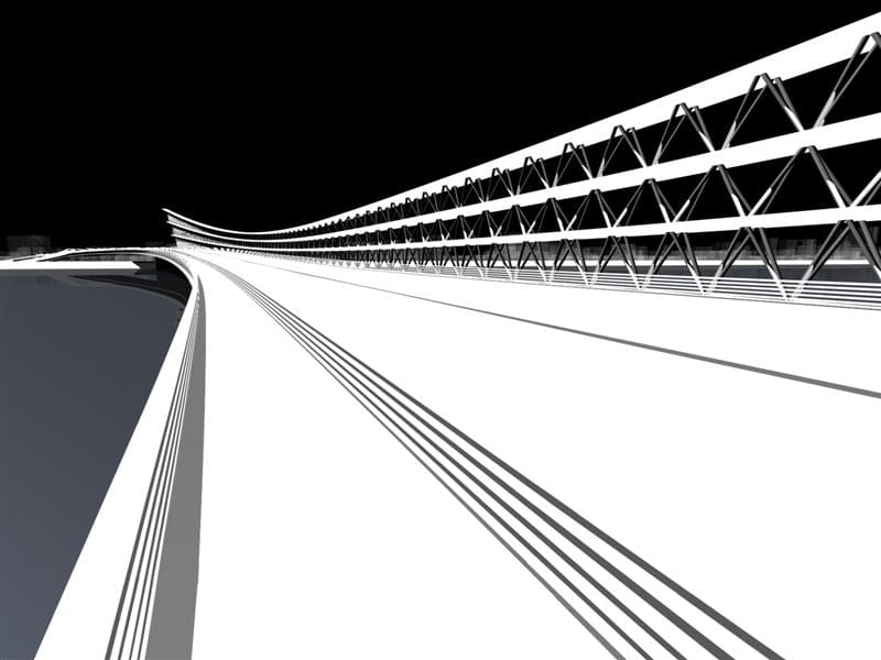
The vertical web of the L section is placed on the outer side of the curved deck. This web is made of three steel longitudinal chords; each chord has a rectangular cross section, 2,5 m wide and 0,5 m deep. The height of these longitudinal chords is variable with relation to the deck. The maximum vertical distance from the deck to the upper chord is 23,7 m. Therefore, the effective depth of the deck is increased, because a deck 2,5 m deep would not be able to resist a main span of 116,0 m. To be effective these three chords must have shear stiffness, and they must be interconnected with each other and to the horizontal part of the deck. In order not to have a very high continuous steel wall, a “diagrid” web has been designed. This web is made of steel circular hollow section tubes (CHS), with a diameter of between 300-400 mm, which are placed at an angle and form something like a “tubular network”.
The main piers of the bridge are made of reinforced concrete. The foundation is made of circular concrete piles that go down to the rocky seabed that is 30 m deep.
The dynamic effects of strong winds and also the dynamic action of seismic effects have been taken into consideration in the calculations using some detailed models of the bridge.