Bridges and Viaducts · Continuous or Girder Bridges
Bridge over the Danube
TECHNICAL DATA
LOCATION
D4 Motorway crossing over the Danube River, Bratislava (Slovakia)
Scope of work
Competition, Construction Project and Technical Assistance to the Contractor
Structural type
Straight viaduct
Construction process
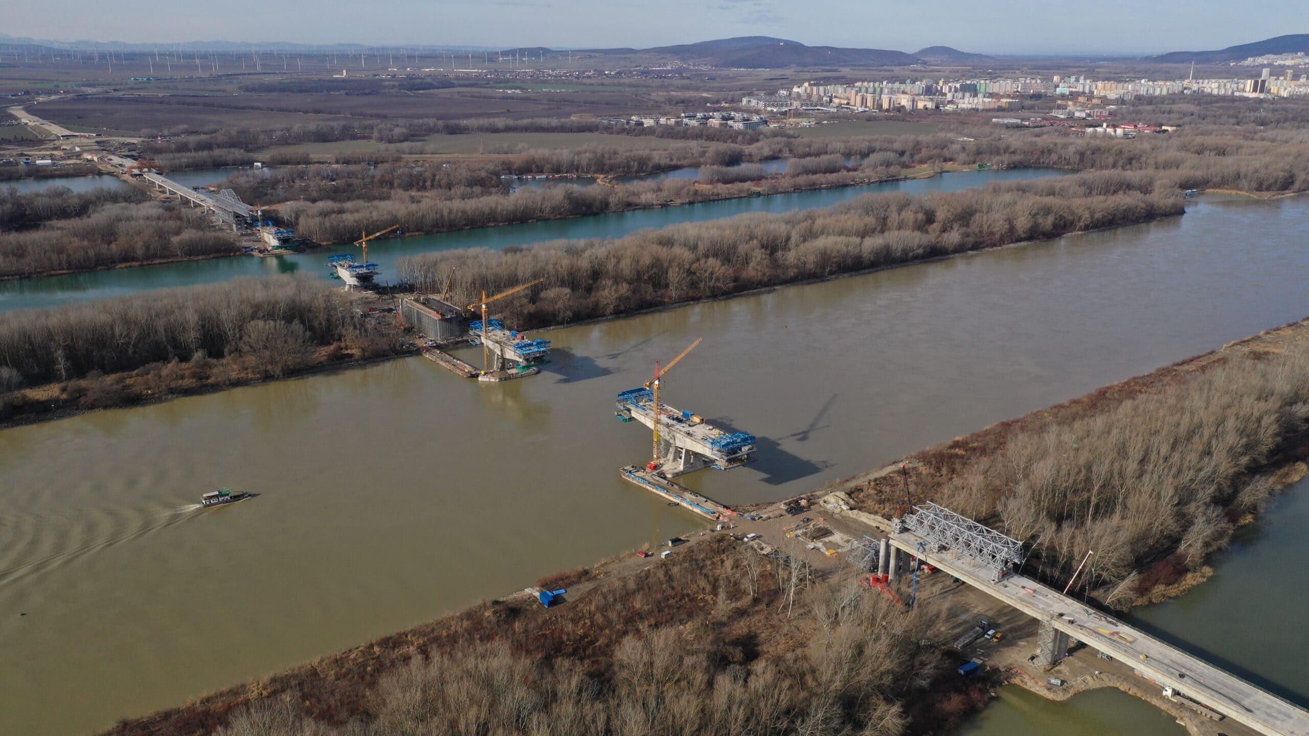
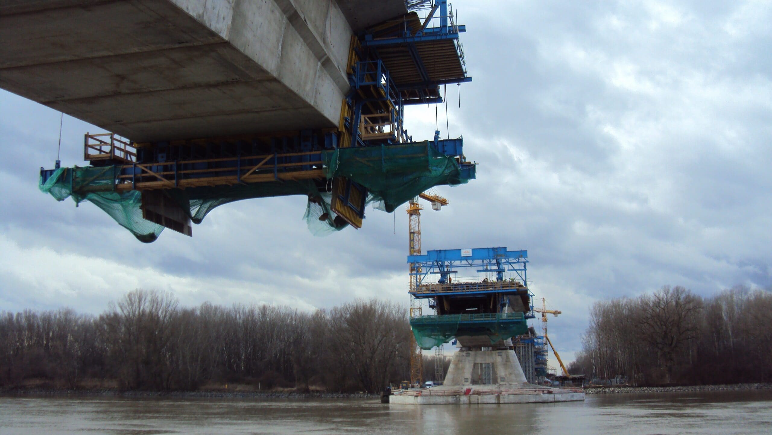
Central box girder: balanced cantilever construction
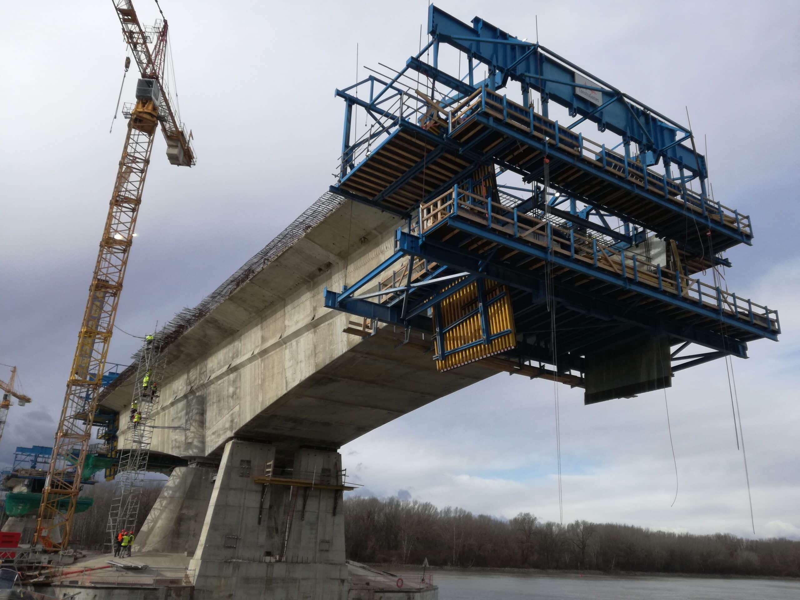
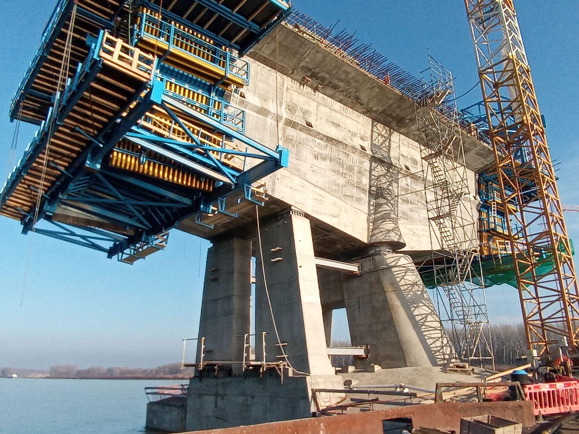
Lateral cantilevers: stage construction using a wing traveler
Total length
430 m
Spans
130+170+130 m
Deck width
35 m
Maximum roadway height
20 m
Overview
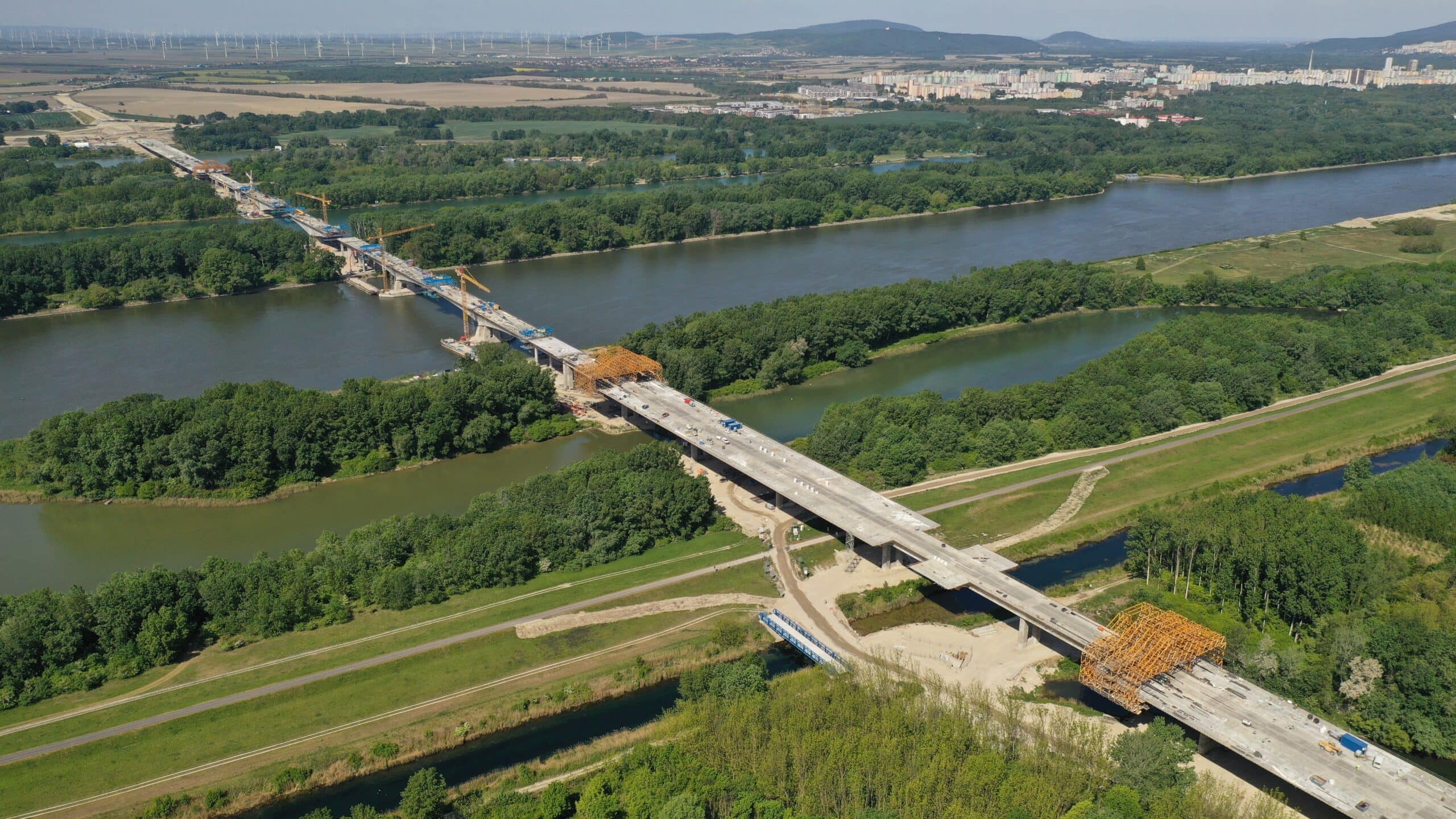
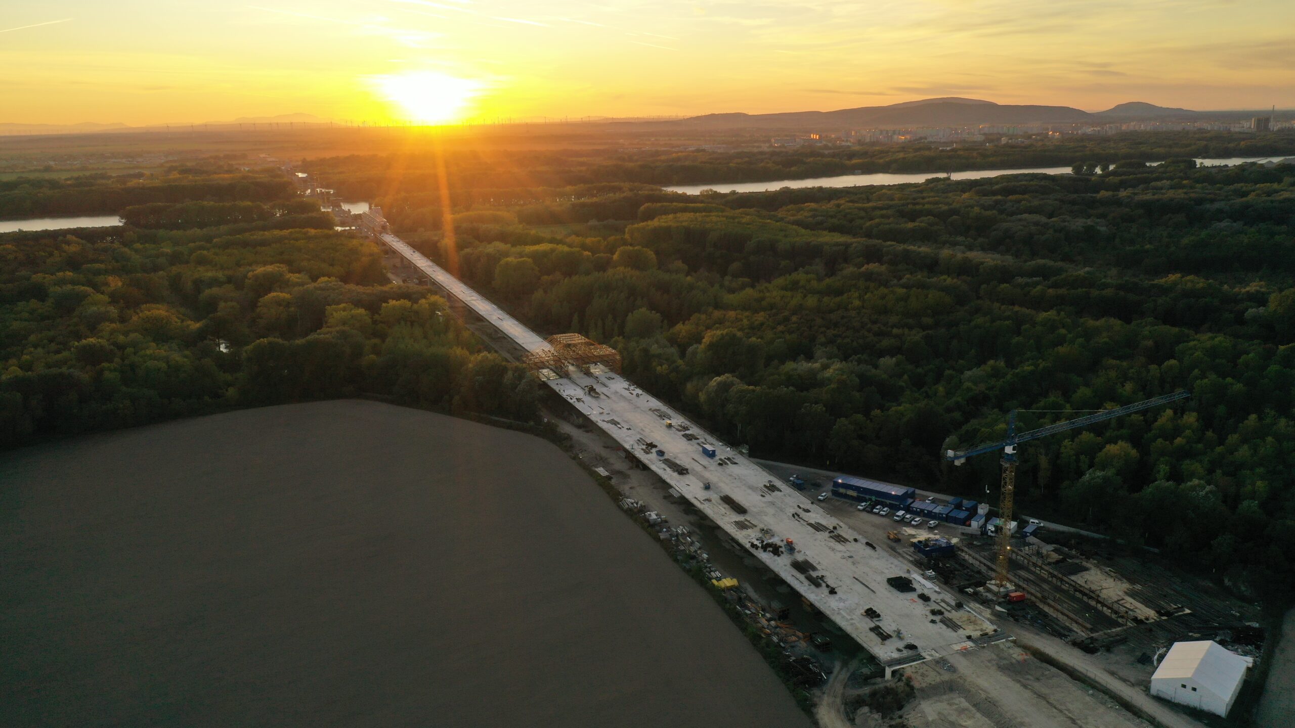
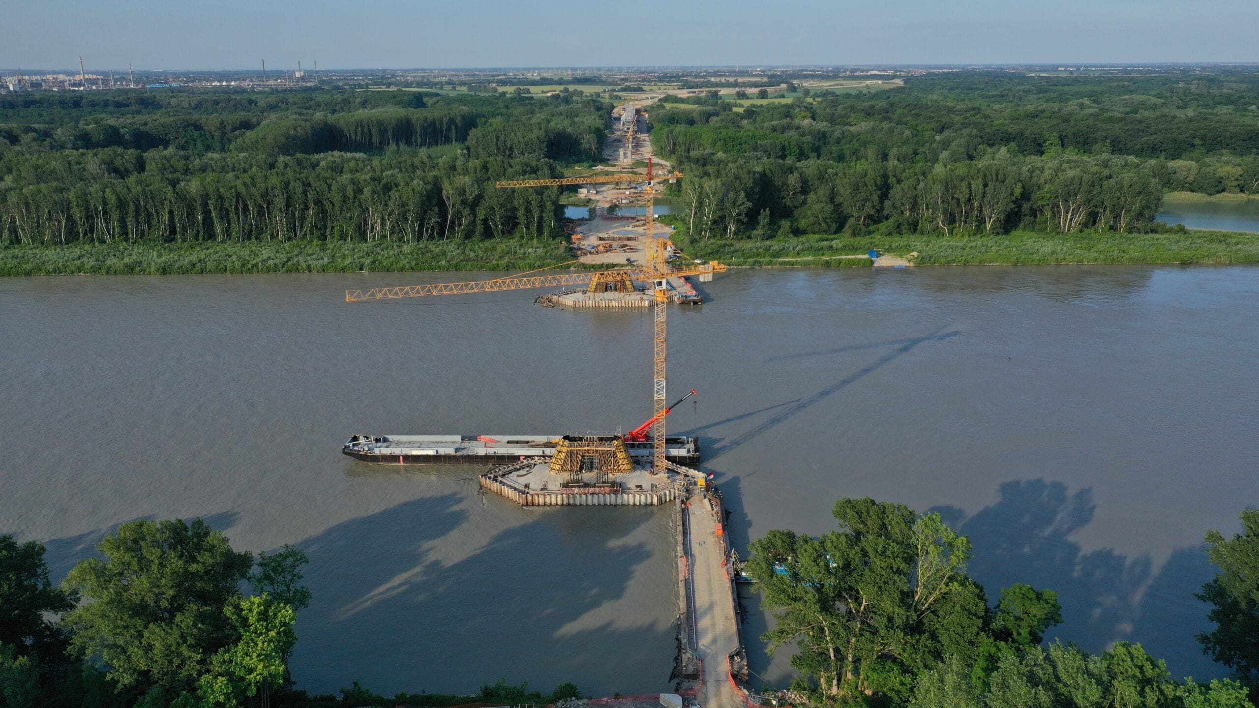
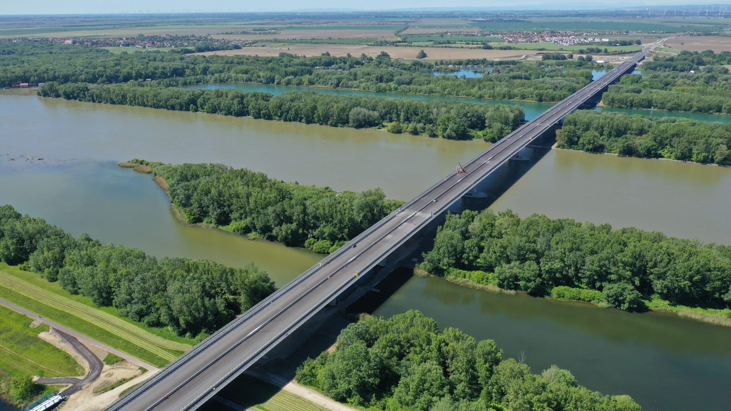
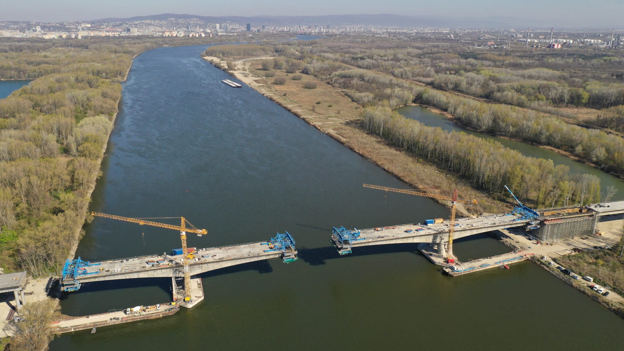
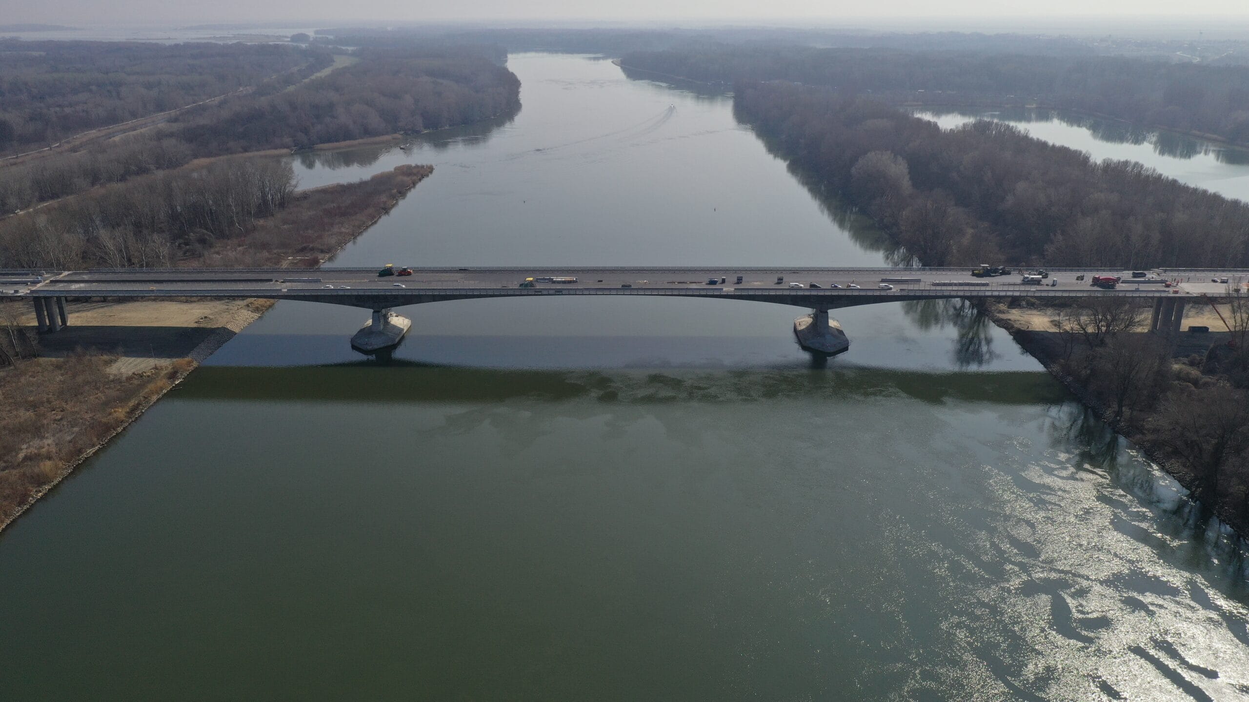
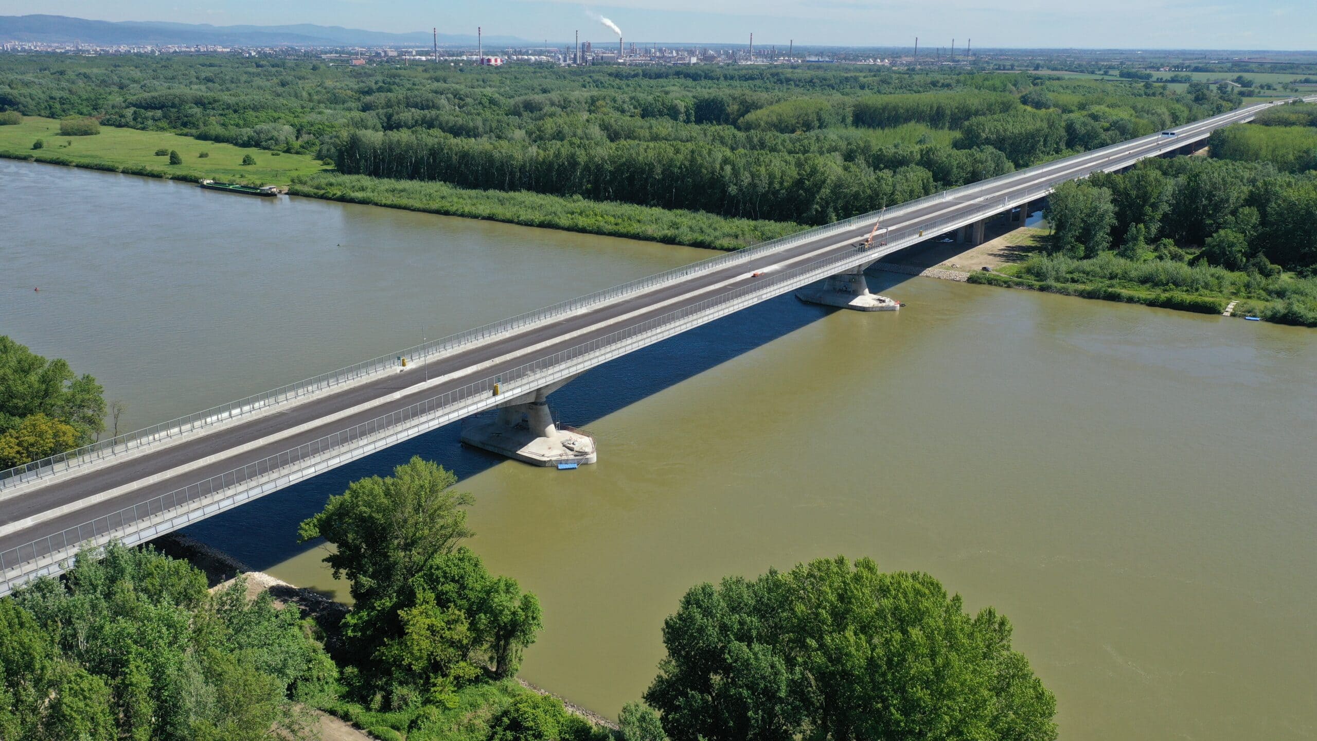
The bridge over the Danube is part of the D4 motorway and is located south of the city of Bratislava (Slovakia). The D4 motorway crossing over the Danube consists of 4 consecutive viaducts, with a combined length of 2,932.5 m.
West Access Viaduct
Crosses the river floodplain and the Jarovecké river branch.
Kayak Viaduct
Crosses an Olympic canoeing channel.
Main Danube Viaduct
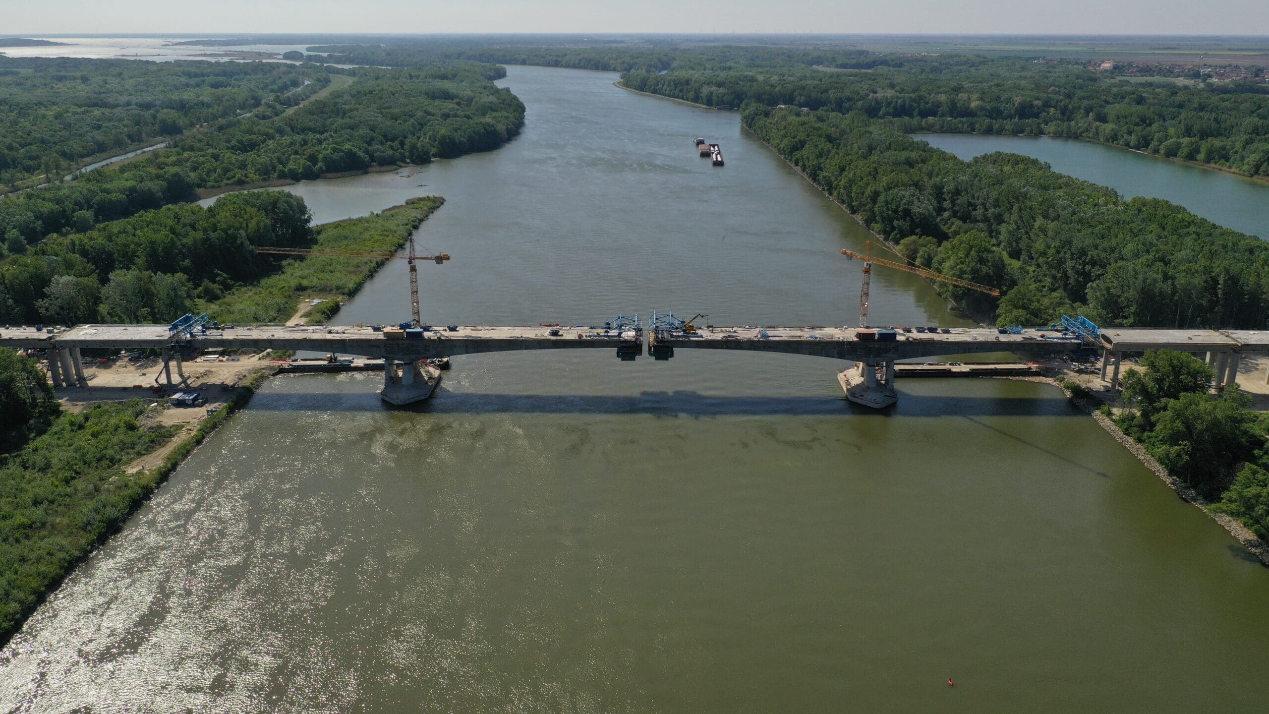
Spans the main channel of the Danube with 3 spans of 130+170+130 m.
East Access Viaduct
Crosses the floodplain and several river branches, most notably the Biskupické.
It is a single-deck bridge with a total width of 35 m, accommodating 2 carriageways of 11.5 m each, each with 2 lanes of 3.75 m, a 2.00 m outer shoulder and a 1.50 m inner shoulder. The median is 3.00 m wide, and the 4.50 m outer strips carry a sidewalk and a bike lane, 3.0 m wide.
In extraordinary situations, the bridge can carry 3 lanes of 3.5 m with reduced 1.0 m shoulders. River traffic passes under the main span, with a minimum horizontal clearance of 150 m and a vertical clearance of 10 m.
The deck
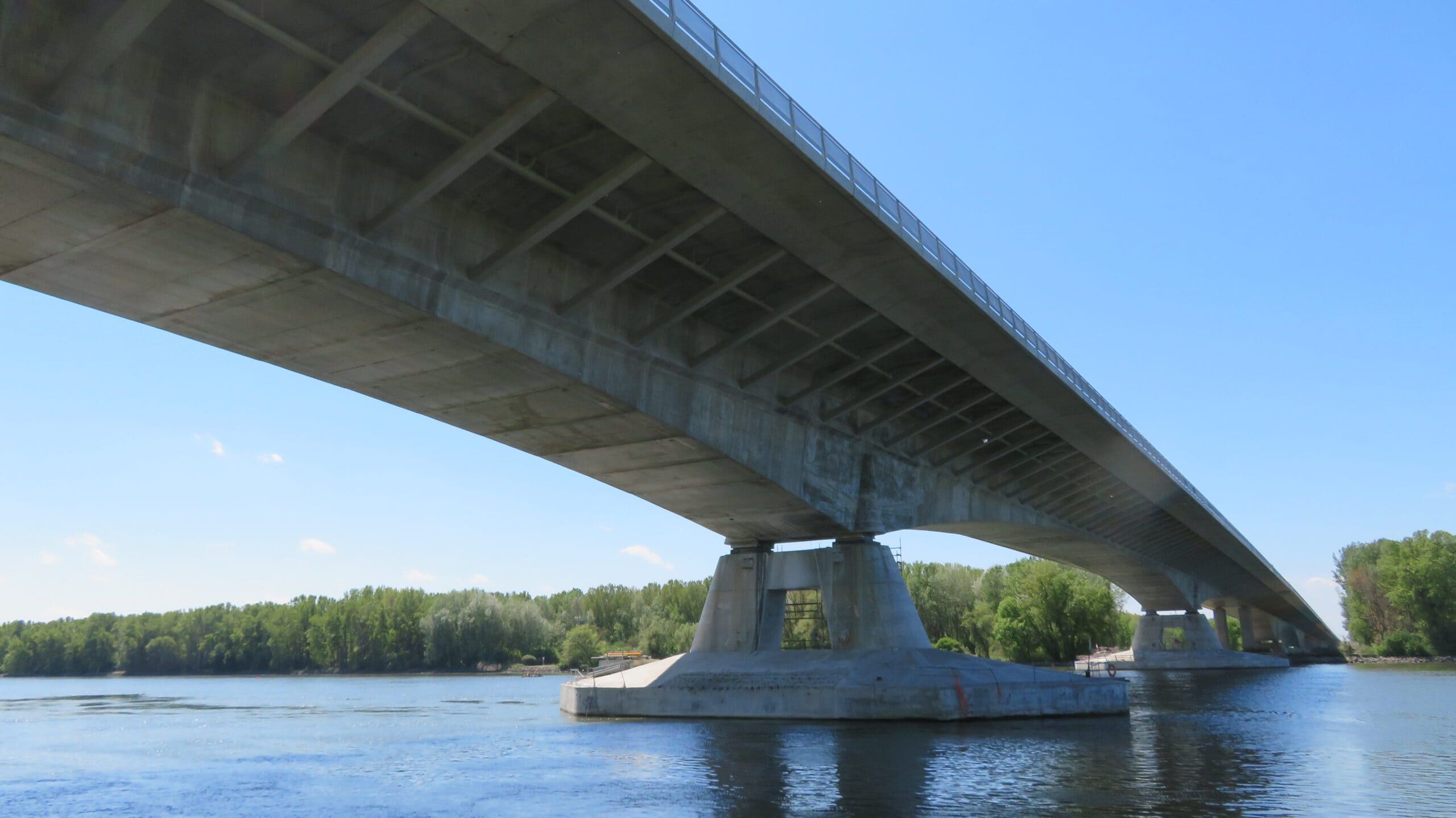
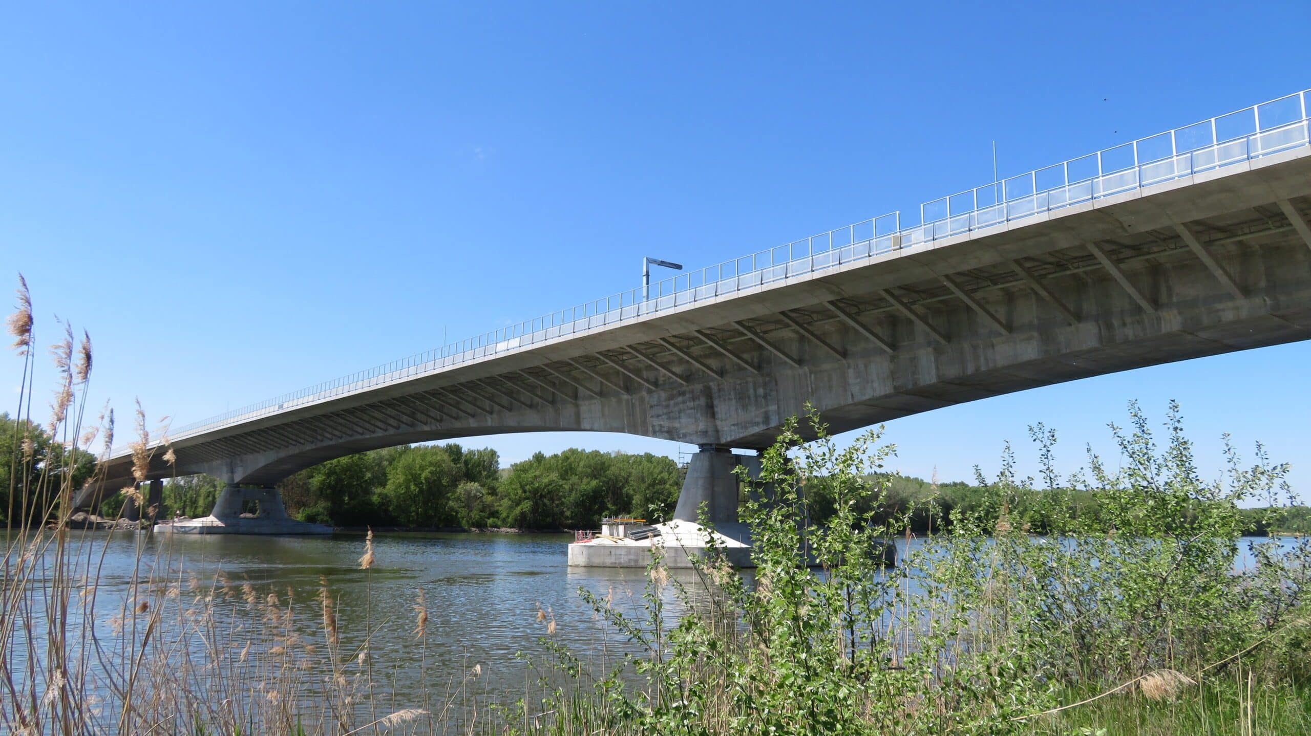
The deck is continuous, with variable depth, and prestressed in both the longitudinal and transverse directions. It has a total width of 35 m. The typical cross-section consists of a central box girder widened on each side by cantilevers supported on precast reinforced concrete struts.
The materials used are: C50/60 concrete in the central box girder and lateral cantilevers, C45/55 concrete in the struts, B550 S reinforcing steel and Y1860 S7 prestressing steel.
Central box girder — Balanced cantilever construction
The deck depth is variable, with a maximum of 10.0 m over the piers and a minimum of 4.3 m at midspan and at the abutments. The depth varies parabolically between the pier section and the section 85 m from the pier, at the center of the main span.
The central box girder is 11.3 m wide at road level, with inclined webs of variable thickness between 0.7 and 1.0 m. Two 2.5 m cantilevers, one on each side, complete the 16.3 m of deck built in the first phase.
Lateral cantilevers — Wing traveler
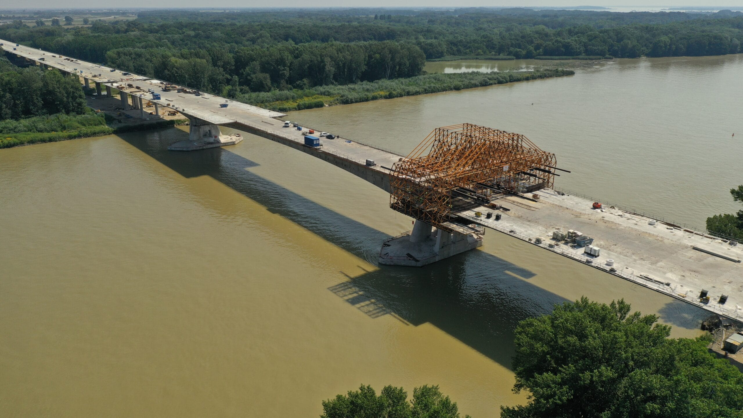
Outside the central width of the deck, the cantilevers are built in a second phase. Each cantilever is a 9.1 m wide, 0.3 m thick concrete slab supported every 5 m by inclined precast struts with a constant 0.5×0.4 m² cross-section and a length of 8.5 m.
Notably, no stiffening elements were required inside the box girder between the webs in the area where the struts bear.
Longitudinal and transverse prestressing
The longitudinal prestressing of the deck is complex and one of the most interesting features of the viaduct. Three types of prestressing can be distinguished:
Isostatic prestressing Phase 1
In the upper slab. Introduced into the central core of the deck during balanced cantilever construction.
62 tendons · 31 strands · 150 mm² per TContinuity prestressing Phase 2
In the lower slab. Introduced into the central core once structural continuity has been established, first in the side spans and then in the central span.
44 tendons per side span · 28 tendons in the central span · 27 strands · 150 mm²Third-phase prestressing Phase 3
In the upper slab of the complete section, except for the central 60 m of the main span, where the cantilevers are not yet built.
20 tendons · 31 strands · 150 mm²Given the type and dimensions of the cantilevers, transverse prestressing was provided through the upper slab, consisting of 4-strand tendons of 150 mm² arranged every 0.8 m along the deck. The tendons are placed in sealed, grouted plastic ducts.
Construction process
The deck was built in two phases. In the first phase, the 16.3 m wide central core of the deck was built; in the second phase, the strut system of the 9.1 m cantilevers on each side. The auxiliary equipment only required support on the bridge substructure and on previously built sections of the deck, minimizing the impact on a surrounding area of high environmental value.
Construction of the T-sections over the piers — Balanced cantilever
First-phase isostatic prestressing. A total of 4 form travelers are used (2 per pier), with 16 pairs of segments per pier and a maximum weight of 5,000 kN per segment.
In-situ construction of the 45 m side sections
Built on conventional ground-supported falsework. Partial continuity prestressing in the lower slab. Once built, they are simply supported on the abutment and a temporary tower.
Connection of the T-sections over the piers with the side sections
Lateral continuity prestressing (phase 2). Removal of the temporary piers of the T-sections.
Connection of the two T-sections at the center of the main span
Central continuity prestressing (phase 2). Full structural continuity of the central core of the deck is established.
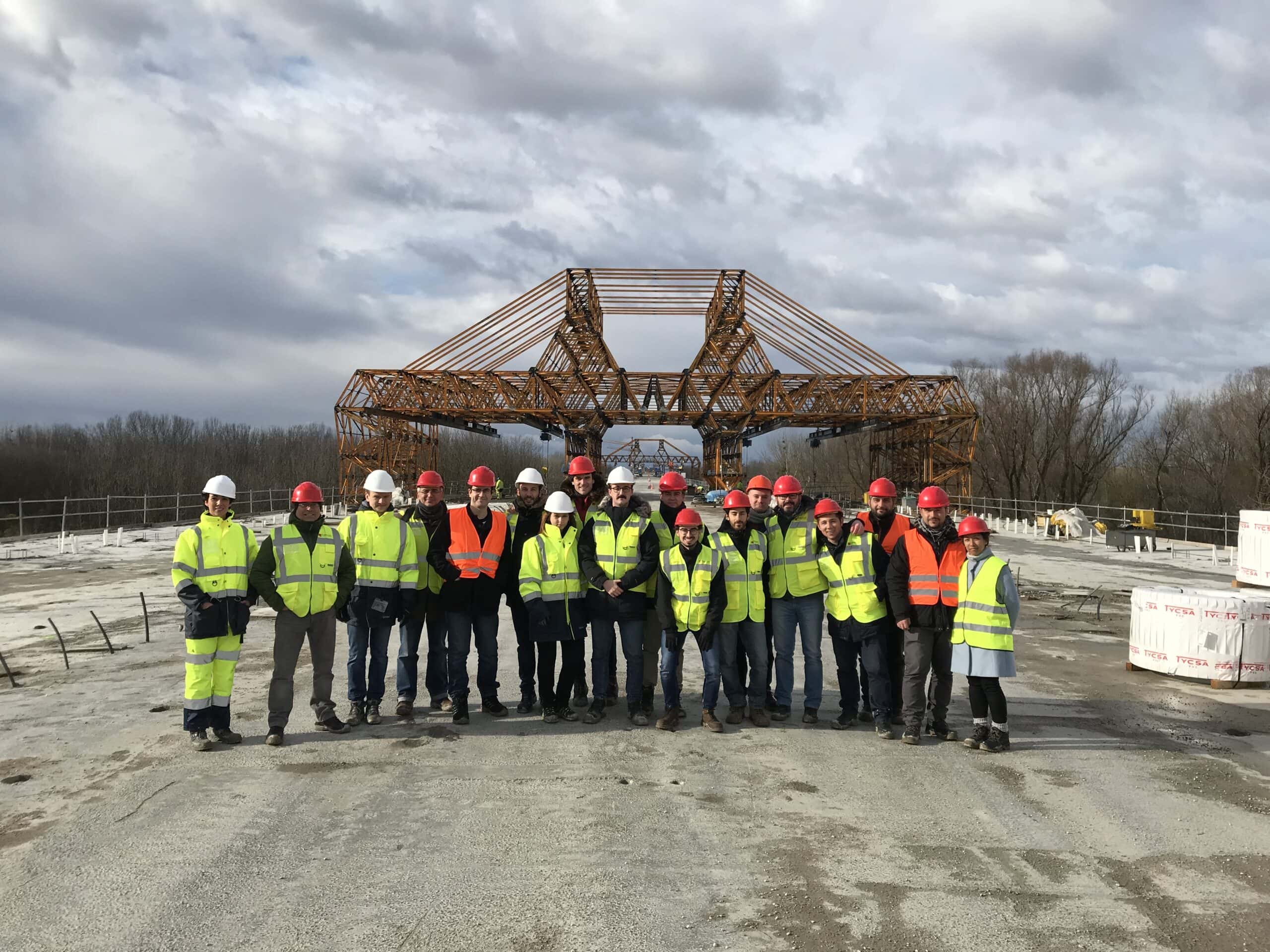
Stage construction of the lateral cantilevers
23 stages in total, advancing from the abutments towards midspan, except for the central 60 m of the main span. A wing traveler sliding on the central core is used.
Third-phase longitudinal prestressing
Introduced into the complete deck section. Final construction of the cantilevers along the central 60 m of the main span.
Substructure
Pier-abutments
The pier-abutments are U-shaped, with two independent columns, one under each web, joined at their base by a reinforced concrete diaphragm. They are founded on 15 piles of 1.2 m diameter and between 25 and 30 m long.
Main piers in the Danube channel
The main piers are located within the permanent channel of the Danube and have an inverted U shape. They are founded on 26 piles of 1.8 m diameter and between 35 and 40 m long. The pile cap has a hydrodynamic hexagonal shape in plan at water level, acting as protection against ship collisions.
The two main piers in the river were built from the top of two artificial islands, formed by sheet pile enclosures filled with gravel from the riverbed itself. The longitudinal fixed point of the deck is located at one of the main piers.