
TAMARACEITE VIADUCT (LAS PALMAS DE GRAN CANARIA)
- Location: GC-2 Northern Access (Las Palmas de Gran Canaria) SEE MAP
- Scope of works: Construction project
- Structural type: Composite arch with variable section and hanging deck
- Construction process: Self-supported arch, deck lifted from the arch
- Overall length: 211,0 m
- Spans: 162,0 m
- Deck width: 30,0
- Deck maximum height: 25,0 m
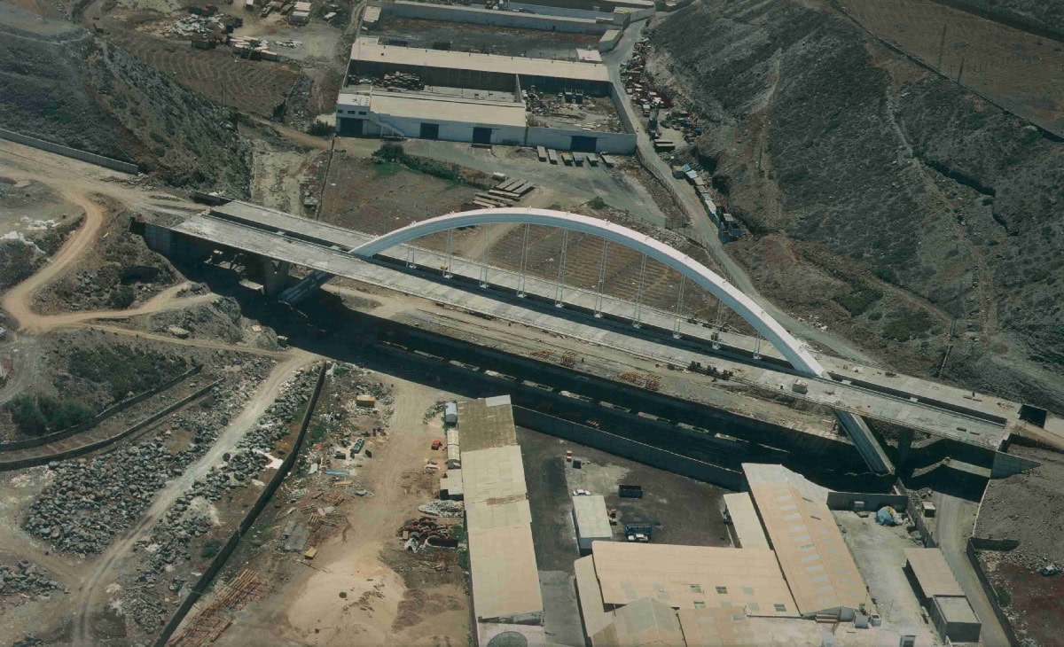
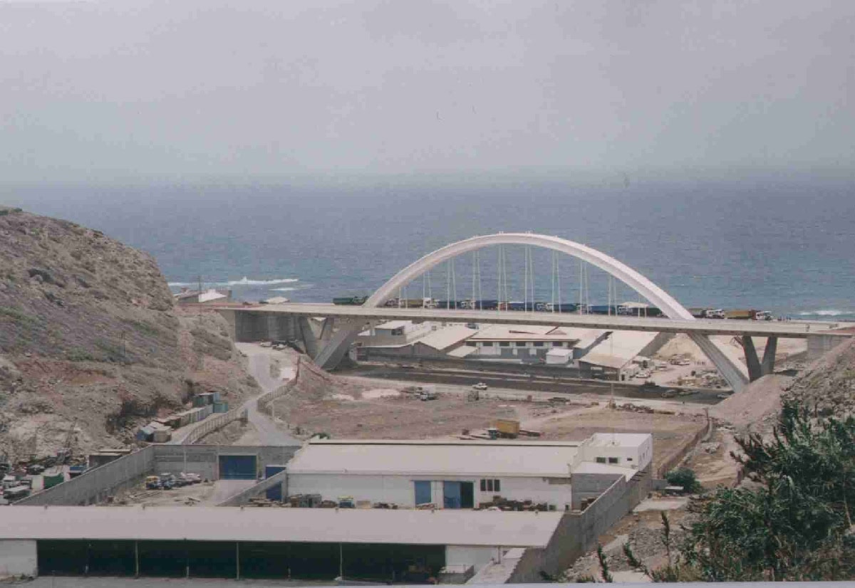
This viaduct is part of the North Access to the city of Las Palmas de Gran Canaria and to La Luz harbour, carrying the said highway over the valley known as Barranco del Rincón or Tamaraceite.
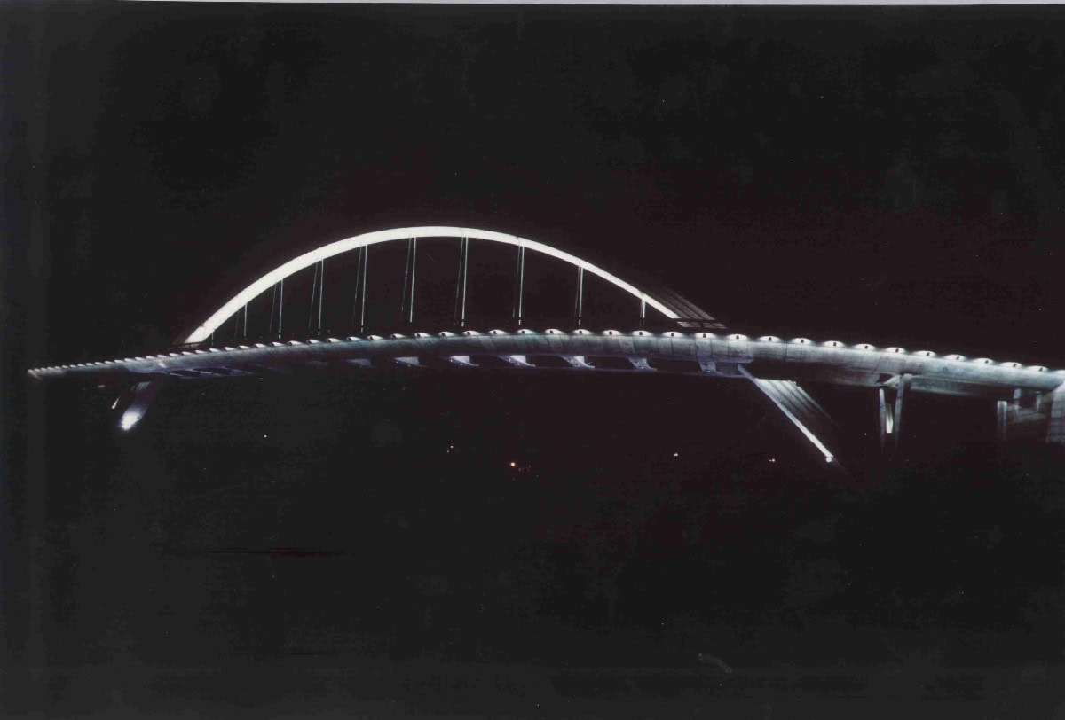
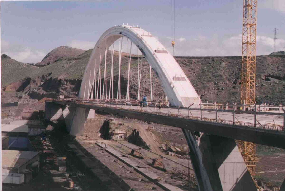
The structure consists of a composite arch with a span of 162 m and a rise 41.0 m. The deck hangs from the arch and is supported by twelve pairs of cables or hangers. The deck is a 30 m wide post-tensioned deck with a span length of 211 m.
The arch is fixed in its ends to solid concrete pedestals resting on footings 12 x 16 m and 2.50 m in depth. The cross section is a box with constant width of 3.6 m, except for the 18.3 m adjacent to the ends where the width varies between 3.6 and 6.5 m. The depth of the arch varies from 2.75 m at the crown to 4.0 m at the bottom ends.
The deck is supported by twelve pairs of hangers and also by two direct bearings on the arch, two piers and the two abutments.
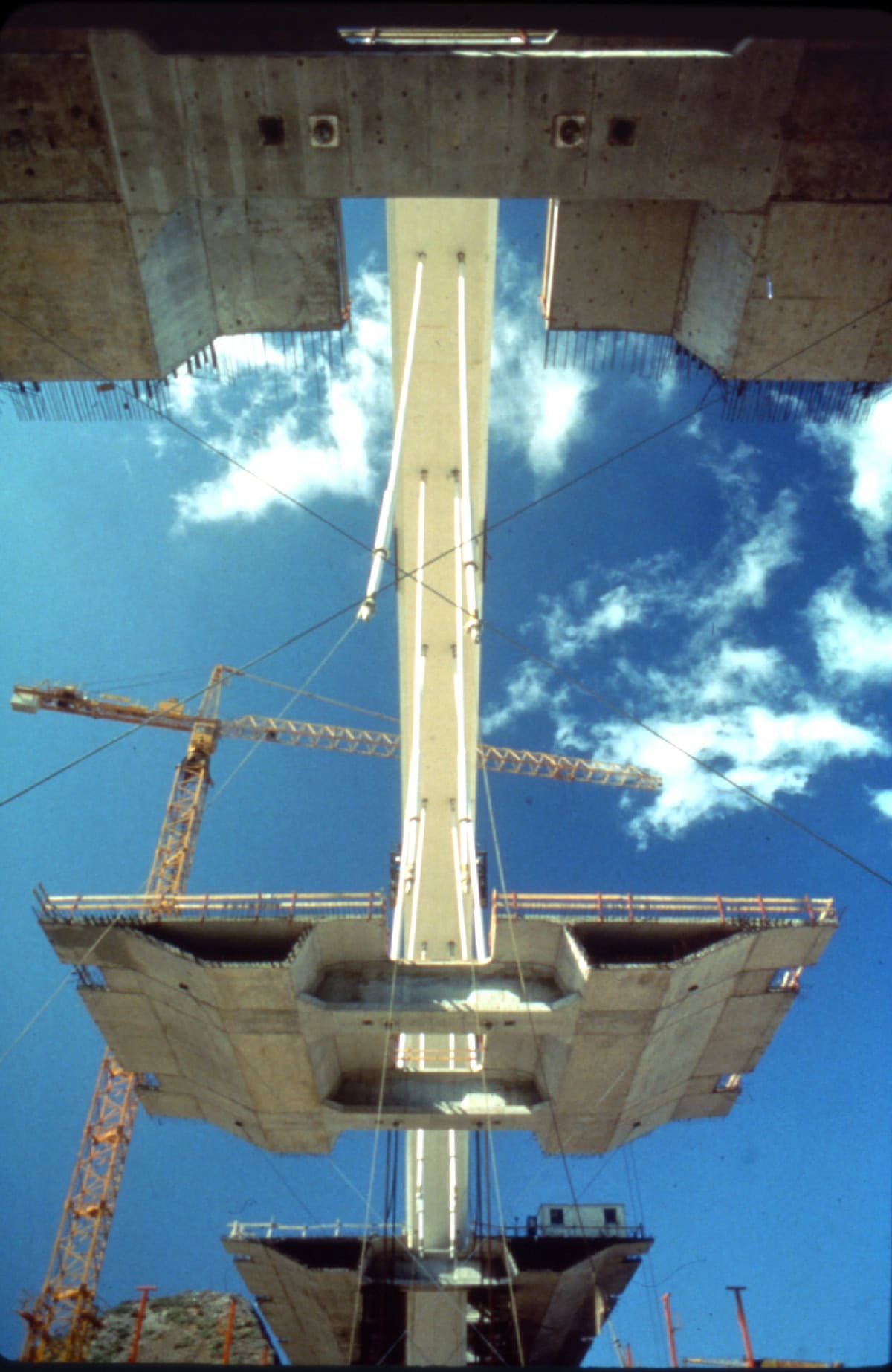
The hangers, located each 10.15 m as per horizontal projection, are provided with variable transversal slope for each pair in order to keep the same distance at the hanging point on the top face of the arch as at the anchorage point on the deck.
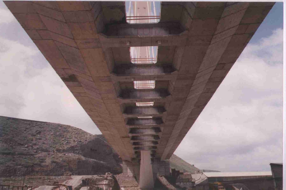
The deck is post-tensioned longitudinally as well as transversally – except over the abutments-. It consists of two single-cell boxes 12.75 m wide, symmetrical between them, which are connected by transversal beams placed generally each 10.15 m, matching the anchorage points of the hangers. The depth of the deck is 2.27m at its centreline, and decreases towards the lateral edges at a transversal slope of 2%.
The piers are 1 m thick walls, which transversally keep a “V” shape. The deck is supported by them using neoprene-teflon bearings. The piers are placed over the solid pedestals of the arch.
Each abutment consists of a stem wall and lateral wingwalls, with unidirectional sliding neoprene bearings supporting the deck at the top. There are also lateral and longitudinal seismic restraints in both abutments.
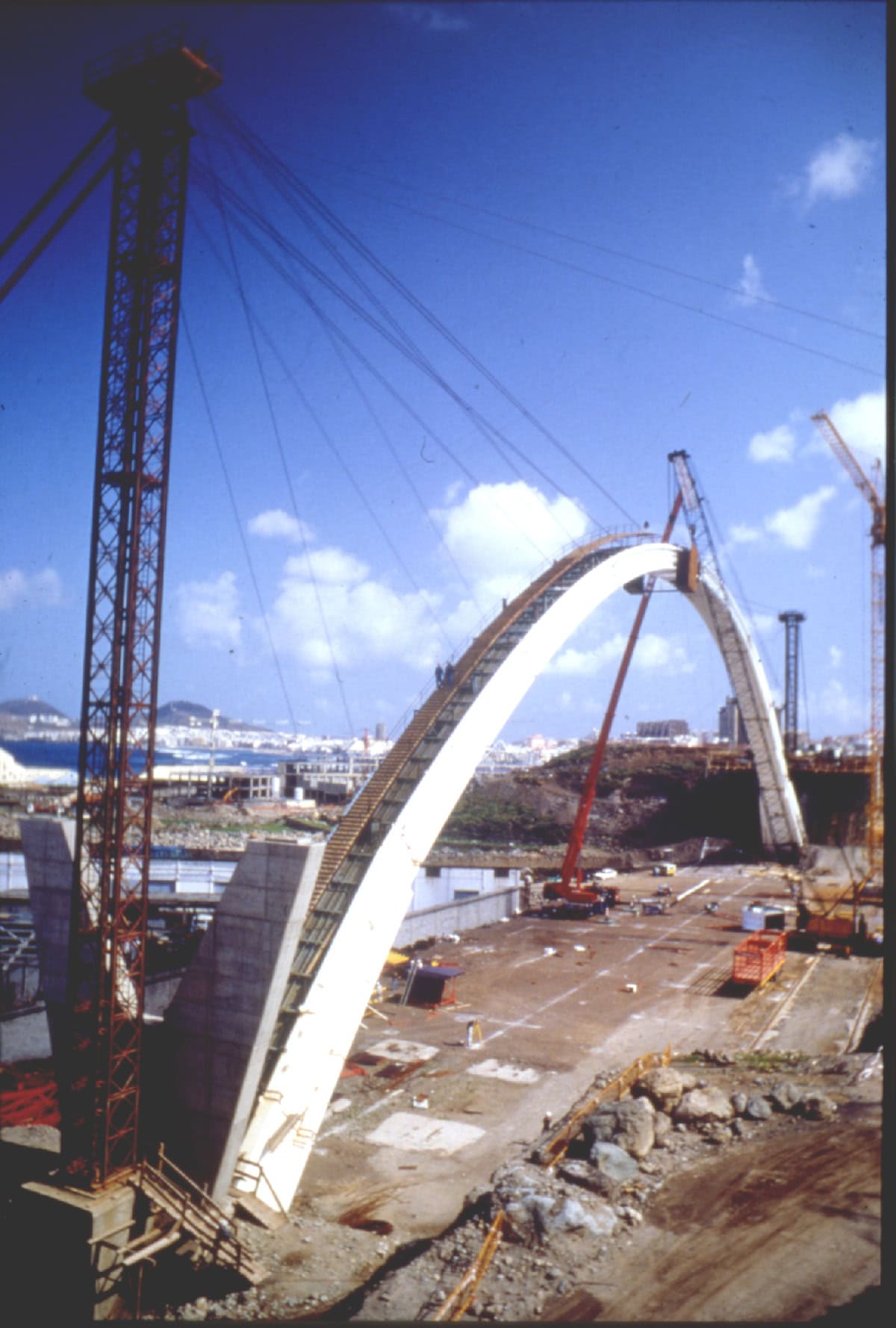
After the completion of the foundations and stem walls of the abutments, the 13 sections of the steel arch are assembled. The assembly is carried out with temporary restraints provided by cables connected to temporary towers. Once the steel arch is completed, concrete is poured in so that the arch acts as a self-formwork. The concrete pouring starts at the bottom ends and finalizes at the crown.
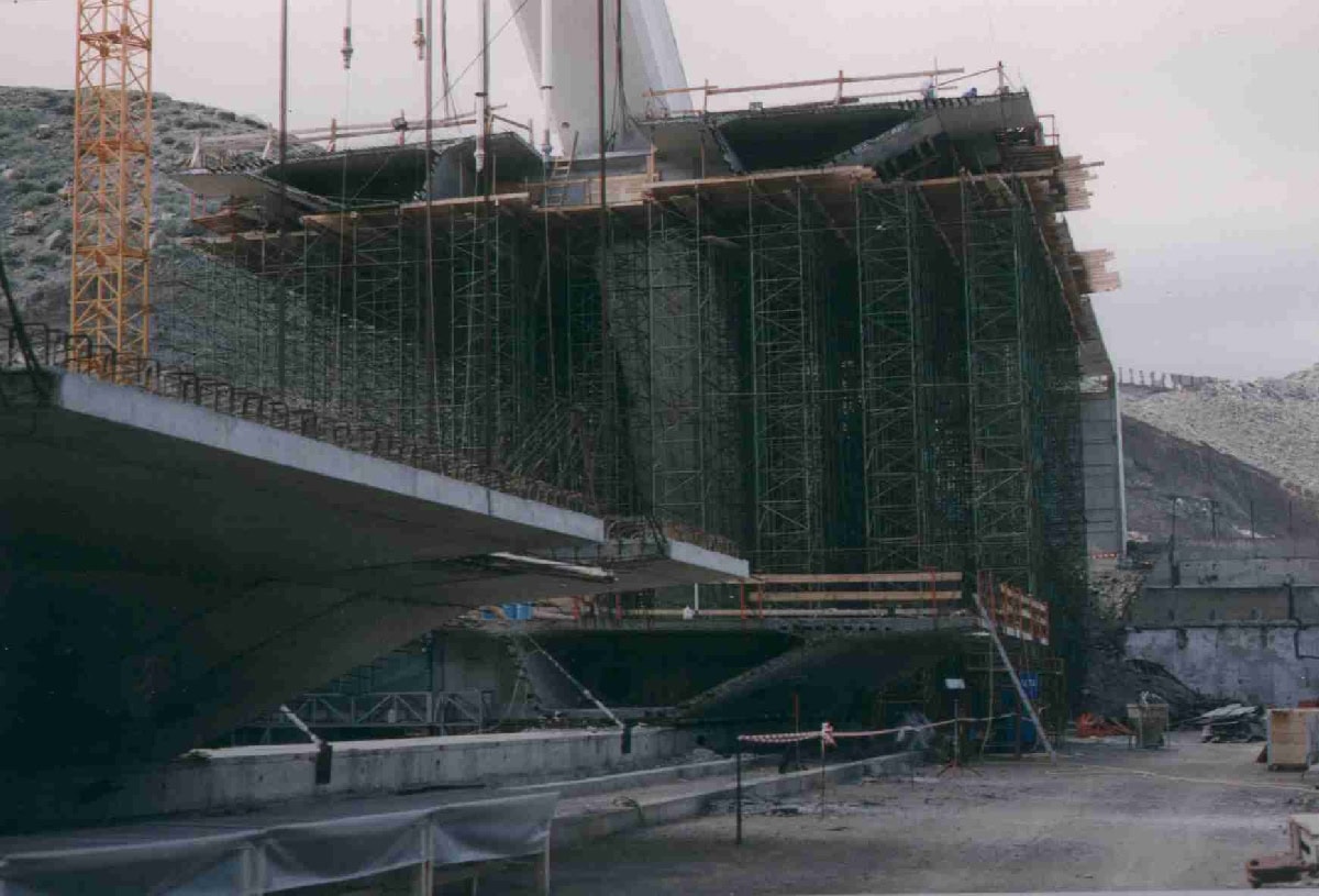
During the concrete pouring of the arch, the outer sections of deck are built with temporary formworks. The rest of the deck, divided into 5 sections 18.5 m long, is pre-fabricated on the ground on-site and is lifted later with jacks from the arch. Finally, once the vertical alignment is adjusted, all the deck sections are interconnected. After that, the longitudinal post-tensioning is undertaken.