
Bridges and Viaducts · PEDESTRIAN BRIDGES
Pedestrian Bridges over the M-30 (Madrid)

TECHNICAL DATA
LOCATION
M-30 (MADRID)
Scope of work
Detailed design
Structural type
Reinforced concrete arches
Construction process
Erection of precast segments
Total length
130.0 m
Spans
103 m
Deck width
3.0 m
Maximum deck height
11.0 m
Project description
In the 1970s, several pedestrian bridges were designed and built over the eastern arc of the M-30 (now Avenida de La Paz) to improve pedestrian connections across it. Among them were the two arch pedestrian bridges designed by José A. Torroja Oficina Técnica, S.A.: two almost identical structures giving access to Ángel Gordillo street (north pedestrian bridge) and to the San Juan Bautista sports centre (south pedestrian bridge), over the four carriageways of the motorway in that section. Both pedestrian bridges were completed in 1978.
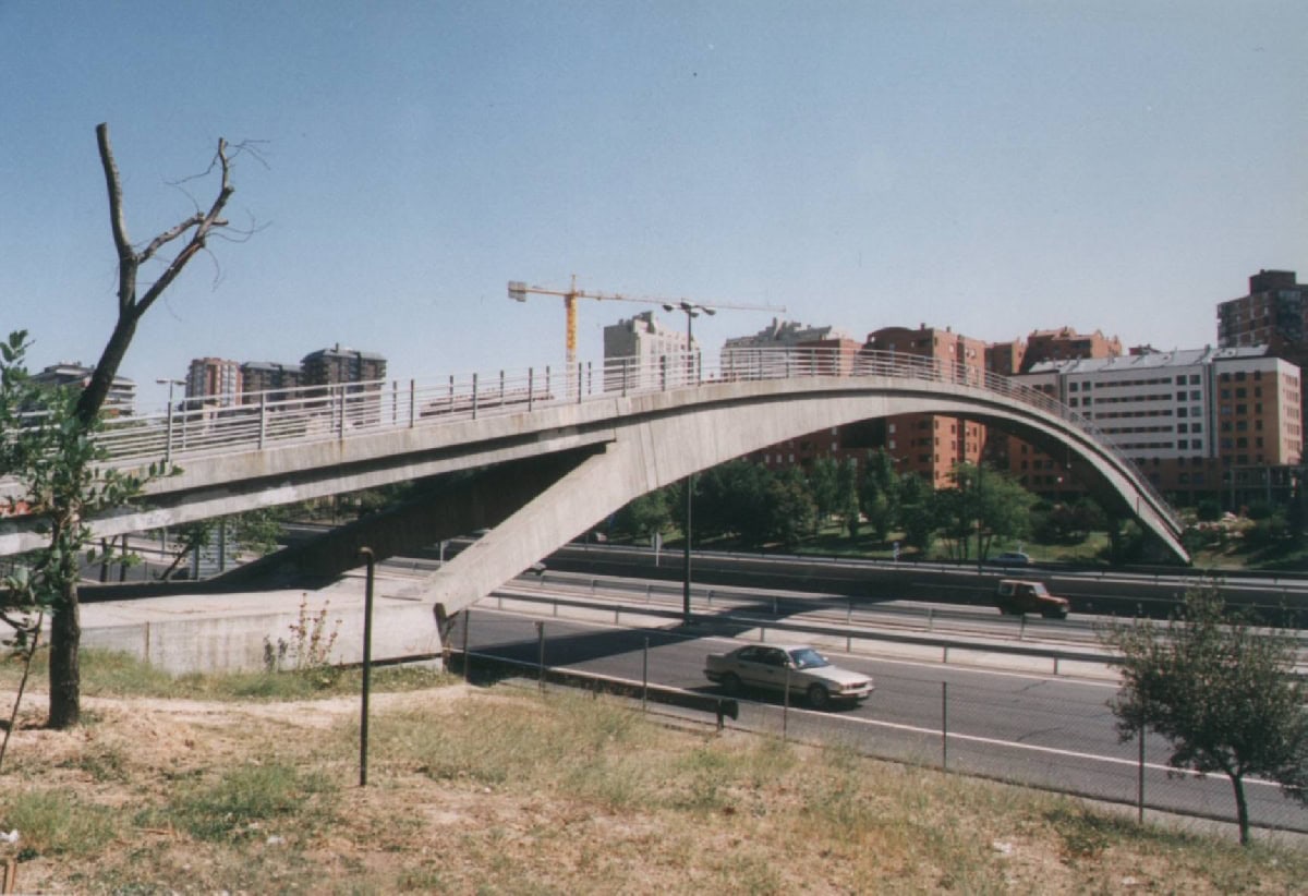
The two pedestrian bridges have become characteristic features of the local urban landscape, perfectly integrated into it. Their majestic arches, spanning 103 m between springings over the four carriageways, have acquired a certain emblematic character thanks to the boldness, simplicity and elegance of the structural solution.
Each consisted of a two-hinged reinforced concrete arch with a span of 103.0 m and a rise of 10.0 m (a rise-to-span ratio of 1:10), resting on both sides of the M-30, together with reinforced concrete access ramps on both sides.
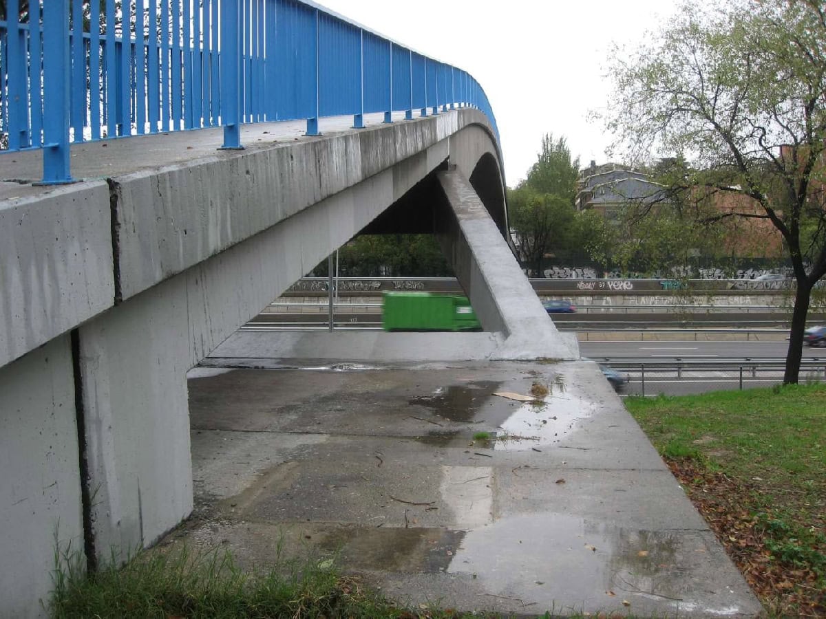
The arch had three parts. The central part was a single-cell box of variable depth, minimum at the crown, and constant width, which itself formed the pedestrian bridge deck. The top slab was 3.0 m wide, and its upper face was the walking surface.
This central part was completed at both ends by a pair of struts supporting it, with a solid rectangular section whose depth decreased towards the springings, where the hinges were located. The struts, fixed to the central part at the haunches of the arch (maximum depth), rested at their lower end on the foundation blocks through plastic hinges. In plan, their axes were oblique to the arch axis, opening symmetrically towards the springings, where they were braced to each other by a prestressed concrete tie. Each pair of struts and its tie formed a triangular cell that gave the arch transverse stability. Both banks had deep foundations. The structure was completed by the side access ramps to the central part of the arch.
The arches of both pedestrian bridges had an ingenious movable abutment system. In both structures, the west abutment of the arch was a sliding slab resting below on a foundation slab and at the front against a vertical stop. This allowed a pair of horizontal jacks to be placed between the movable slab (in recesses provided for this purpose) and the rear reaction stop. It was conceived to load the arch by elastic closure after connecting its precast segments, and also to allow a new elastic closure after a period in service, to offset the loss of rise caused by concrete creep over that time. By pushing the movable abutment towards the fixed abutment in a controlled way, the arch would be raised with the desired camber, recovering the rise lost through creep and eliminating the second-order bending caused by this rheological phenomenon.
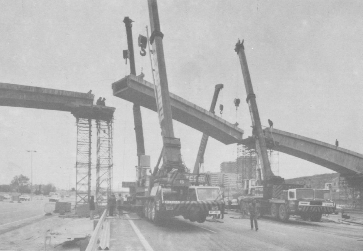
Both arches were precast in six segments that were then erected on site. The box consisted of four segments of similar length, transported to site and placed by crane, connected to each other by segments cast in situ on temporary supports. Once the arch was complete, it was closed elastically and the temporary supports removed, after which the movable abutment was locked and the access ramps placed, completing the structure.