
Bridges and Viaducts · Continuous or Beam
Widening Of The Viaduct Of San Pedro De La Ribera
(Asturias)
technical specifications
Location
Motorway A-8 (Asturias)
Scope of Works
Detailed design and technical assistance during the construction
Structural type
Balanced cantilever bridge (original structure)
Construction process
Widening of the deck from 12 m to 23 m
Overall length
750,0 m
Spans
75,0+4x150,0+75,0 m
Deck width
23,0 after widening
Deck maximum height
90,0 m
Project Description
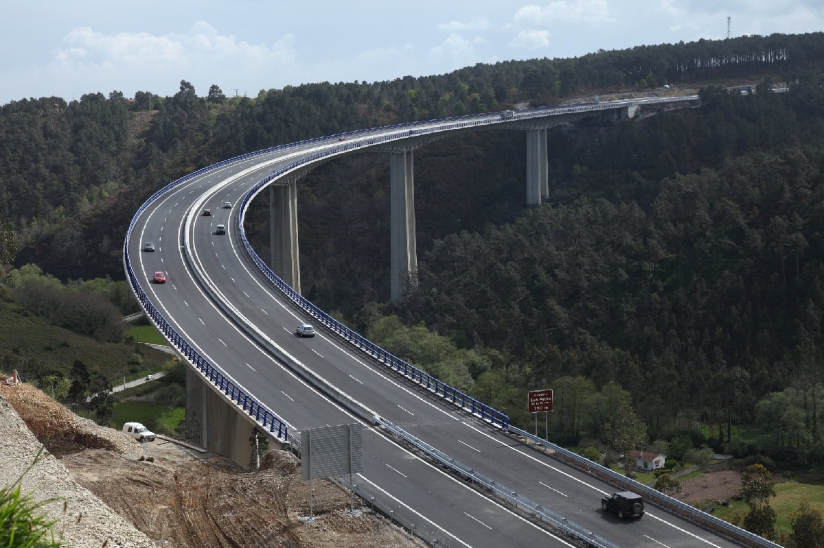
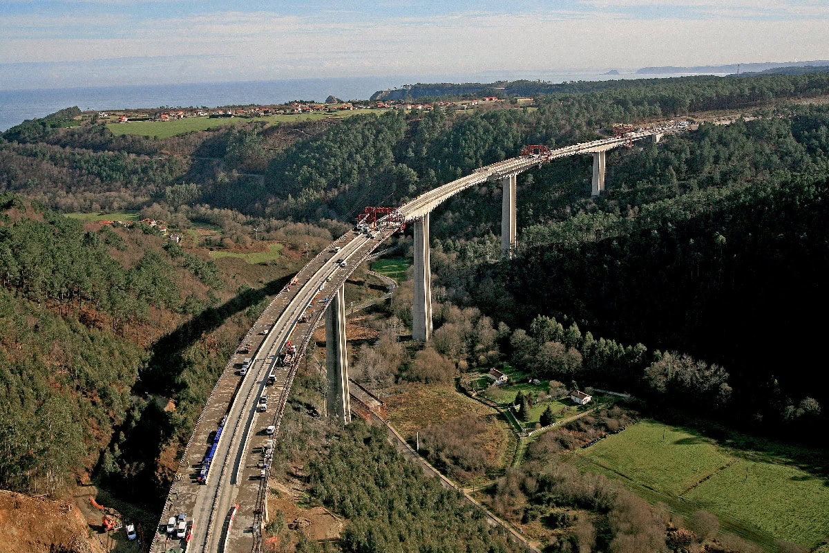
The Viaduct of San Pedro de la Ribera was built in 1994 and crosses the Rio Esqueiro; it is part of the section Las Dueñas-Novellana of the A-8 motorway. The prestressed concrete deck is 750 m long divided into 6 spans: the 4 central spans are 150 m long and the 2 lateral spans are 75 m long. The deck has been widened from 12 m to 23 m, having the new configuration of 2 lanes per direction. The original structure was not expected to be widened, so the widening work has been complex and difficult. The aesthetics of the structure and of the surroundings also had to be taken into account.
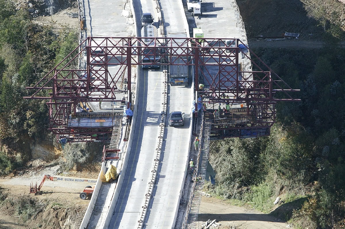
The selected solution for widening the deck had to be defined in order no to interrupt the traffic on the bridge during the construction works. Also the total loads on the foundations had to be supported by the existing foundations.
According to the above mentioned requirements, some detailed calculations were made concerning the substructure (piers, abutments and foundations) using current building norms and regulations. Some wind tunnel tests of the deck and of the piers were also made. The piers were calculated using a refined second order analysis; cracking of the concrete, geometrical and material nonlinearities were considered in these calculations. As a result of the calculations it was found that only minor reinforcements of the foundation terrain of pier P5 had to be undertaken.
Some other detailed calculations of the original deck and of the widened deck were also made. It was found that the existing prestressed system of the deck was not enough to prevent the cracking of the concrete. Also the cracking produced by the shear and torsional forces were not acceptable for the widened structure, particularly because the bridge was in a coastal environment. The Ultimate State Limit was also calculated; the existing reinforcement was not enough to resist the loads due to the widened deck. Also, the shear and torsional forces were too high to be resisted by the existing stirrups of the webs. In accordance with this it was demonstrated that the deck must be strengthened to resist the new loads of the widened deck.
The main elements for the proposed strengthening of the existing deck are the following:
External prestressing system, made up of a group of tendons that run all along the deck and another group of tendons placed over the connection of each pier.
Composite box section placed under the bottom slab of the existing deck. This is to contribute to the flexural resistance of the deck
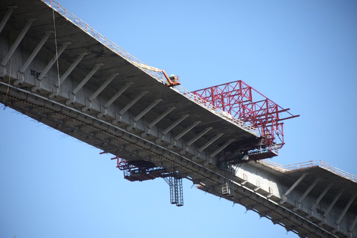
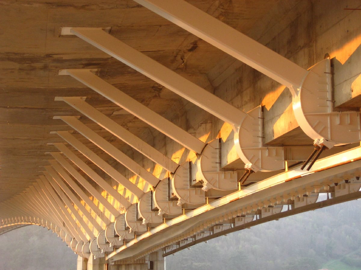
Transverse steel beams connected to the inclined steel columns to support the widening of the upper slab of the existing deck
New central web (0,40 m thick)
Inclined steel columns (struts) and new concrete transverse cantilevers for widening the top slab of the existing deck
Inclined internal diagonals; they transfer the load from the inclined struts to the new central web.
Transverse prestressed system of the upper slab to resist the transverse bending moment of the new cantilevers and act as the tie for the strut and tie system created with the inclined struts.
Transverse concrete beams located on the bottom slab; they resist the horizontal transverse compression produced by the inclined steel columns.
It was decided to build all the new elements at the same time, but on different zones of the deck. This meant that the construction schedule was very complicated but the total delay of the works was reduced.
5 movable scaffoldings and form travellers were used for the widening of the deck. Movable scaffolding n. 1 (68 tons weight and 23 m high) was used for placing the lower box section. 2 movable scaffoldings n. 2 (6 tons weight) moved hanging from the bottom slab of the deck and were used for tensioning the new central web and the inclined diagonals and finally 2 movable form travellers n. 3 (68 tons weight), were used for placing the inclined steel columns and for pouring the concrete every 5 m of the new transverse cantilevers.