
Bridges and Viaducts · Arch Bridges
Lanjarón Viaduct (Granada)
TECHNICAL DATA
LOCATION
A-348, access road to Lanjarón (Granada)
Scope of work
Detailed design
Structural type
Steel tied arch with composite lower deck
Construction process
Launching and "fishing" from the opposite abutment
Total length
112.6 m
Span
112.6 m
Deck width
13.7 m
Maximum deck height
80.0 m
Project description
Within the Dúrcal–Izbor section of the new Granada–Motril motorway, a branch road was planned to improve access to the town of Lanjarón. This branch road meets a deep ravine formed by the Lanjarón River, known as the Tablate ravine.
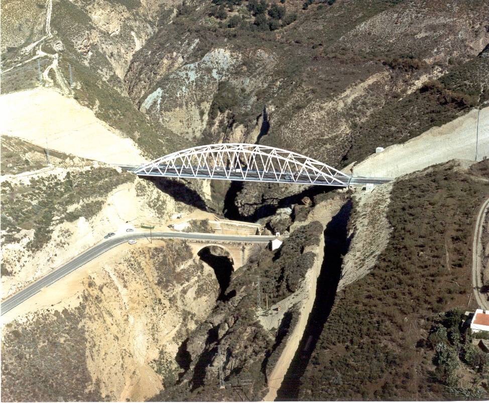
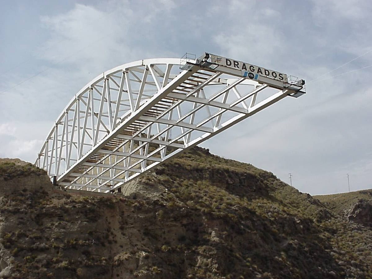
The structure designed and finally built is a composite bridge: an arch tied by its own deck, which transmits only vertical reactions to the ground. Both the arch and the deck consist of two ribs and a series of cross beams. Those of the arch stiffen and connect the two ribs, while those of the deck support the concrete slab that carries the traffic. The arch and the deck are connected by hangers. Because of their triangulated arrangement, the hangers are slightly compressed under some load cases, so they are made of steel box sections.
The bridge has a span of 112.6 m and a rise of 15 m. The cross-section comprises two 3.5 m lanes, with shoulders, barriers and sidewalks.
As neither temporary nor permanent occupation of the ravine was possible, the erection options were extremely limited and practically reduced to launching. However, as this is a single-span bridge, the usual launching procedure could not be used.
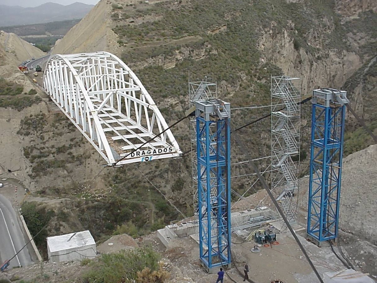
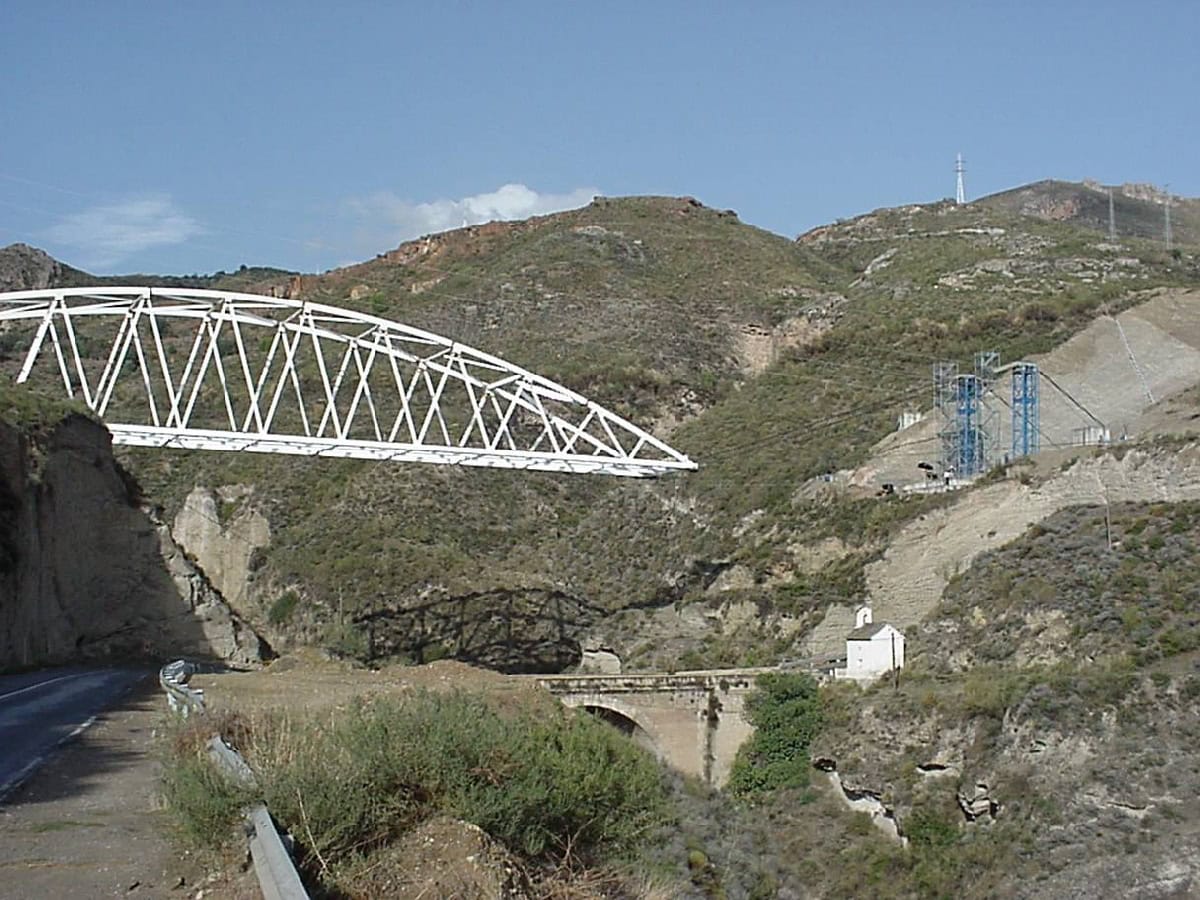
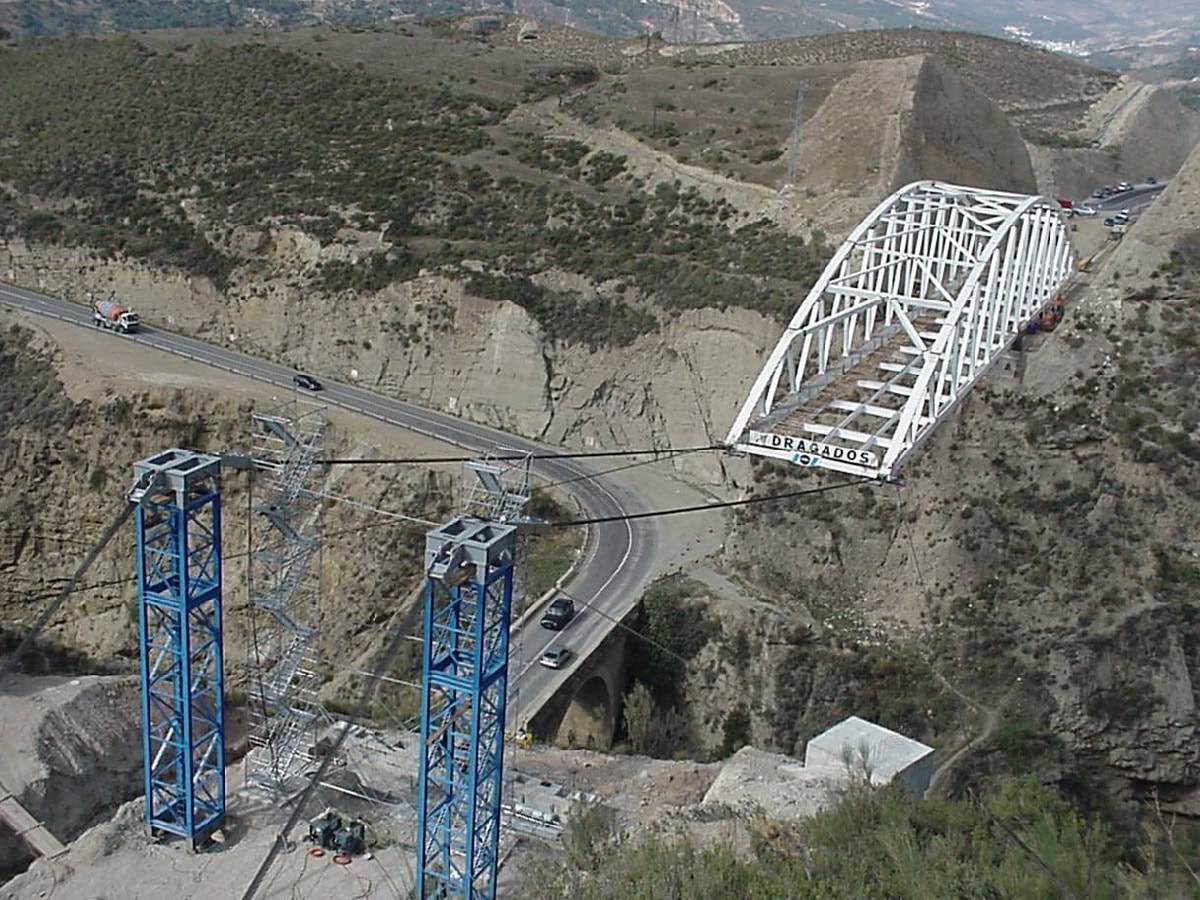
The steel structure was assembled on the ground on one side of the ravine. Once assembled, the bridge rests on skids at one end and at mid-length, and is pushed until half of it is over the ravine. Beyond this point further pushing is impossible: the structure could not withstand higher stresses, nor would it be stable, as an excessively large counterweight would be needed at the end on the ground. To continue the launch, a 15 m high tower is placed on the opposite slope, from which support cables are run to the cantilevered end of the bridge. The bridge is then supported by these cables and by one of its supports on the ground, since in this situation the other support is removed. Back-stay cables are installed to balance the resultant force of the support cables.
By acting on the back-stays with launching jacks and on the support cables, the bridge is moved into place. The basic process consists of lifting the bridge by taking in support cable and moving it forward by paying out back-stay cable.
The construction process is quite unusual, as the deck is placed in its final position by means of a “fishing rod”.