
Bridges and Viaducts · Motorway or Railway Structures
Braehead Bridge, M8 (Glasgow, Scotland)
Back to list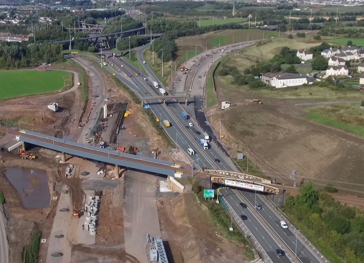
Project description
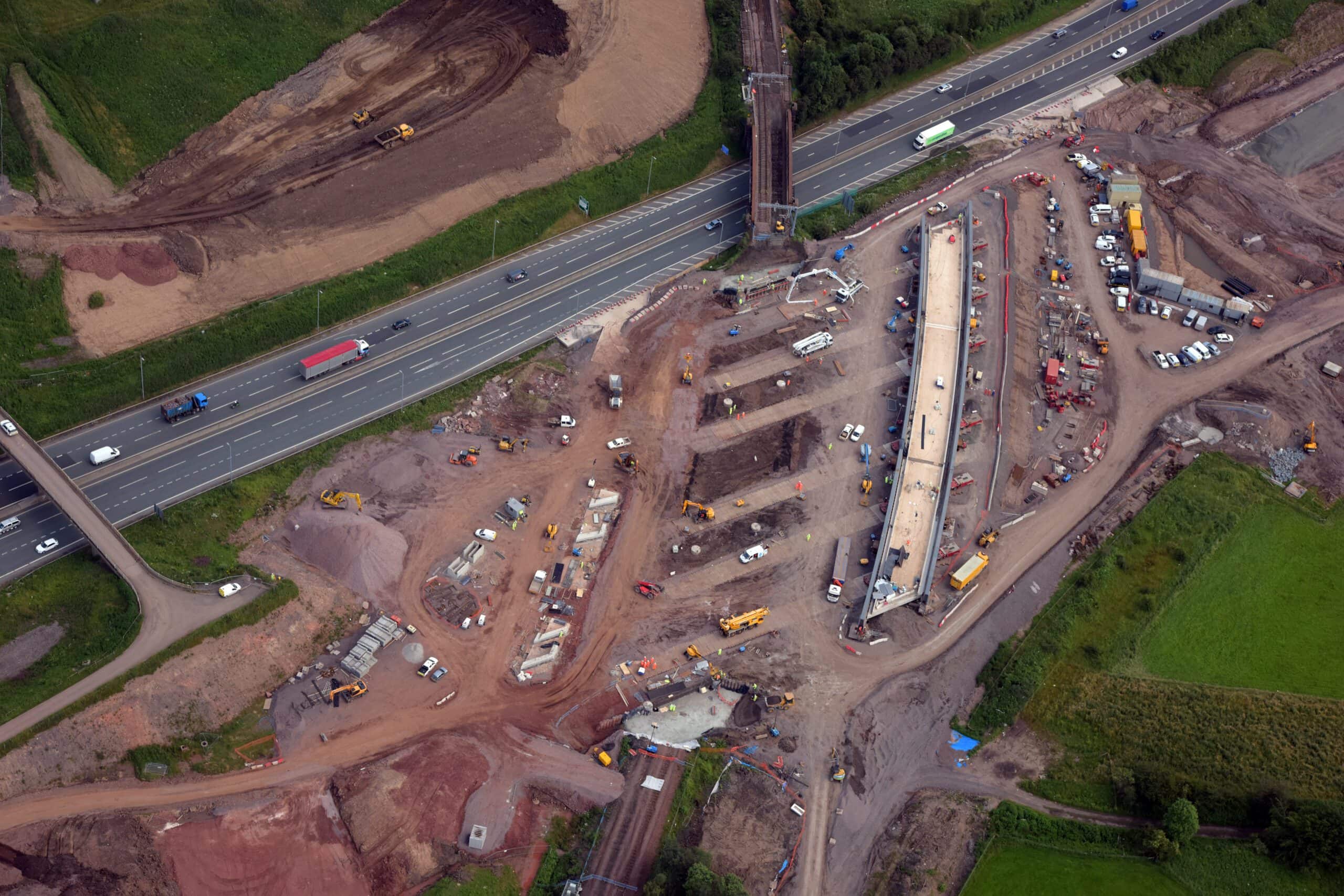
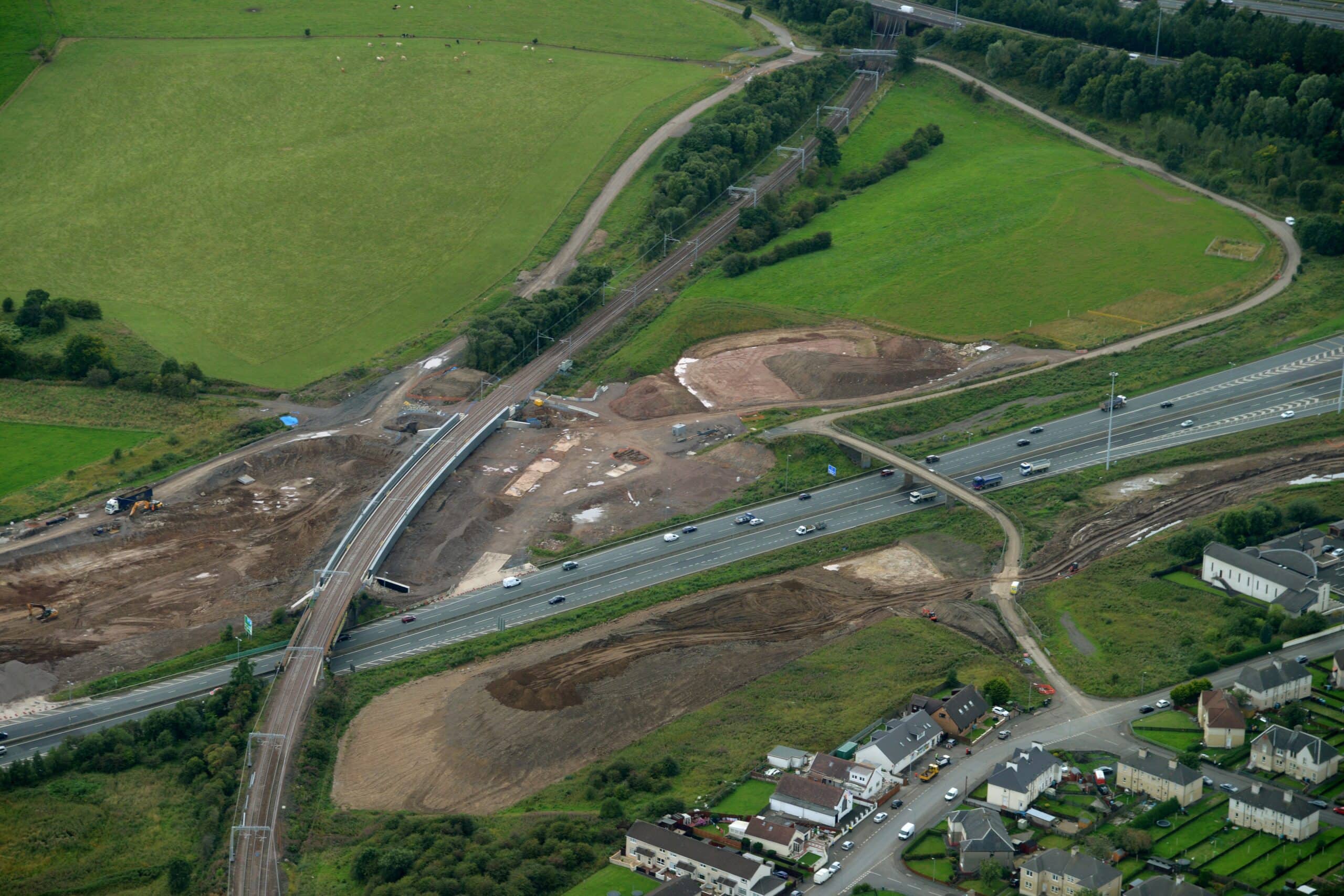
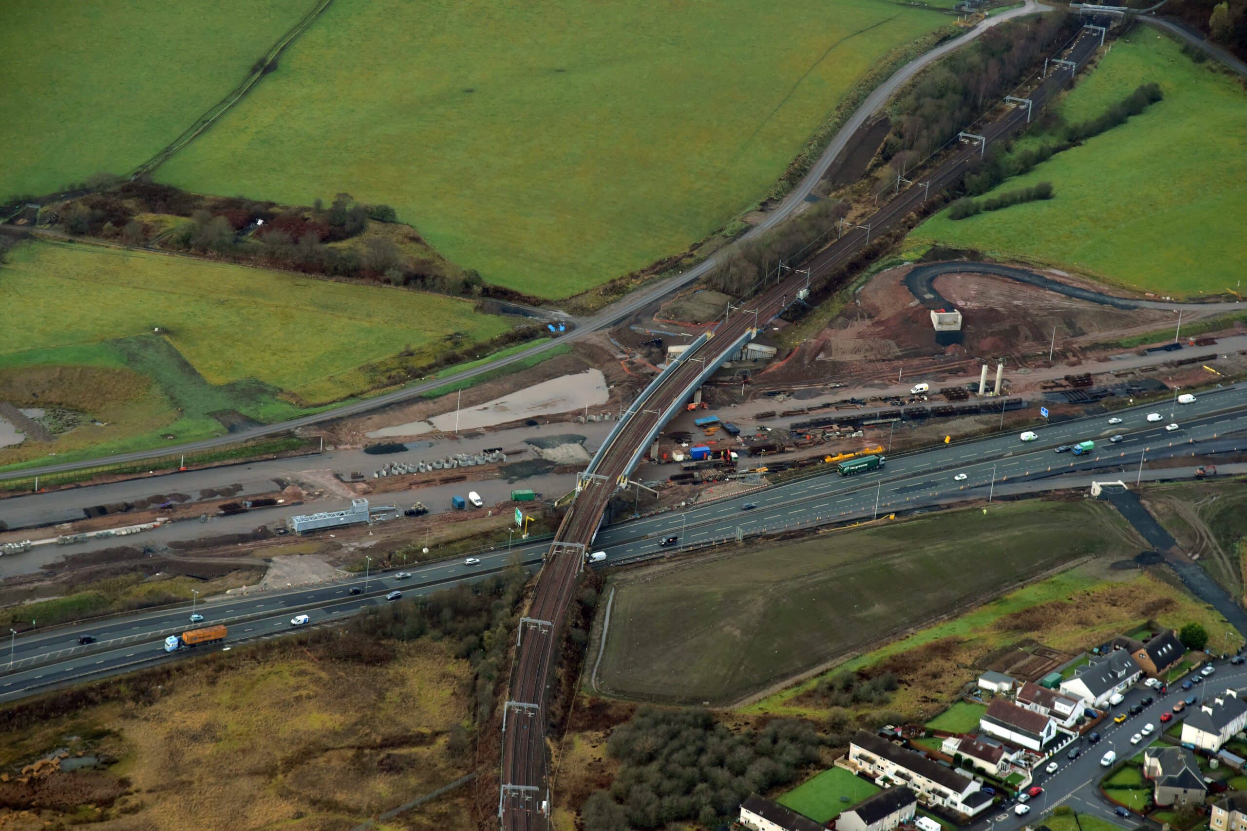
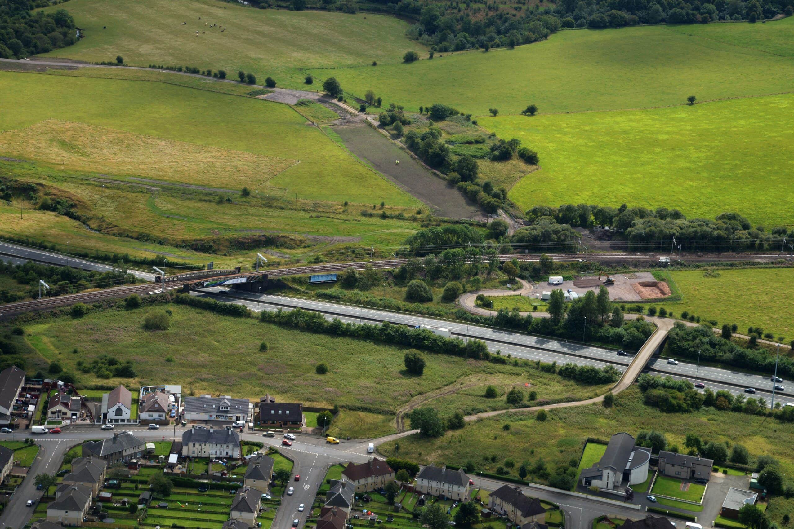
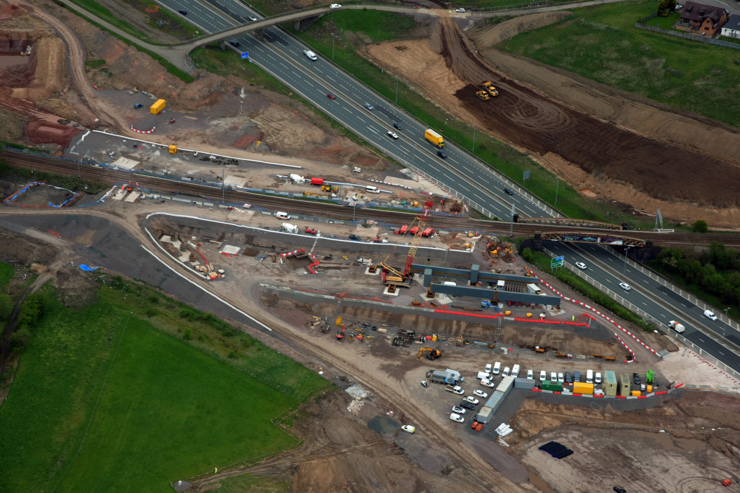
Structure S105 is a 126 m long railway bridge carrying the two tracks of the Rutherglen–Coatbridge line over the new M8 motorway at Braehead, Glasgow. The bridge keeps the railway line on its original alignment, replacing the existing embankment.
The bridge has 3 spans of 43+46+37 m. It crosses the M8 main carriageway and slip roads with a sharp 45º skew, keeping a minimum clearance of 5.7 m above the motorway. The total deck width is 13.20 m. The deck is curved in plan, on a 690 m radius, and in elevation it lies on a rising gradient of 1.3%.
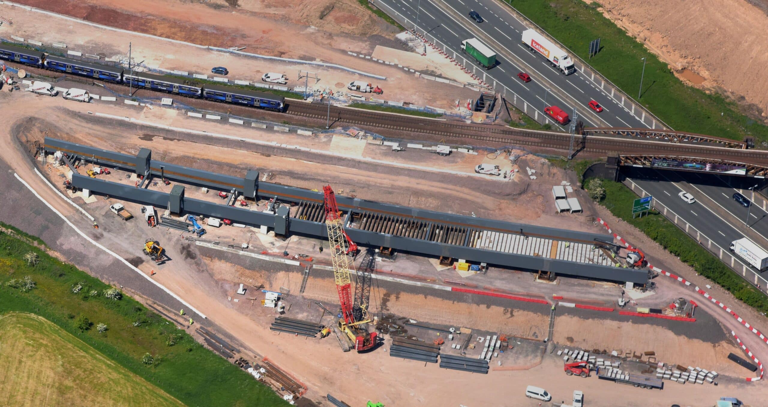
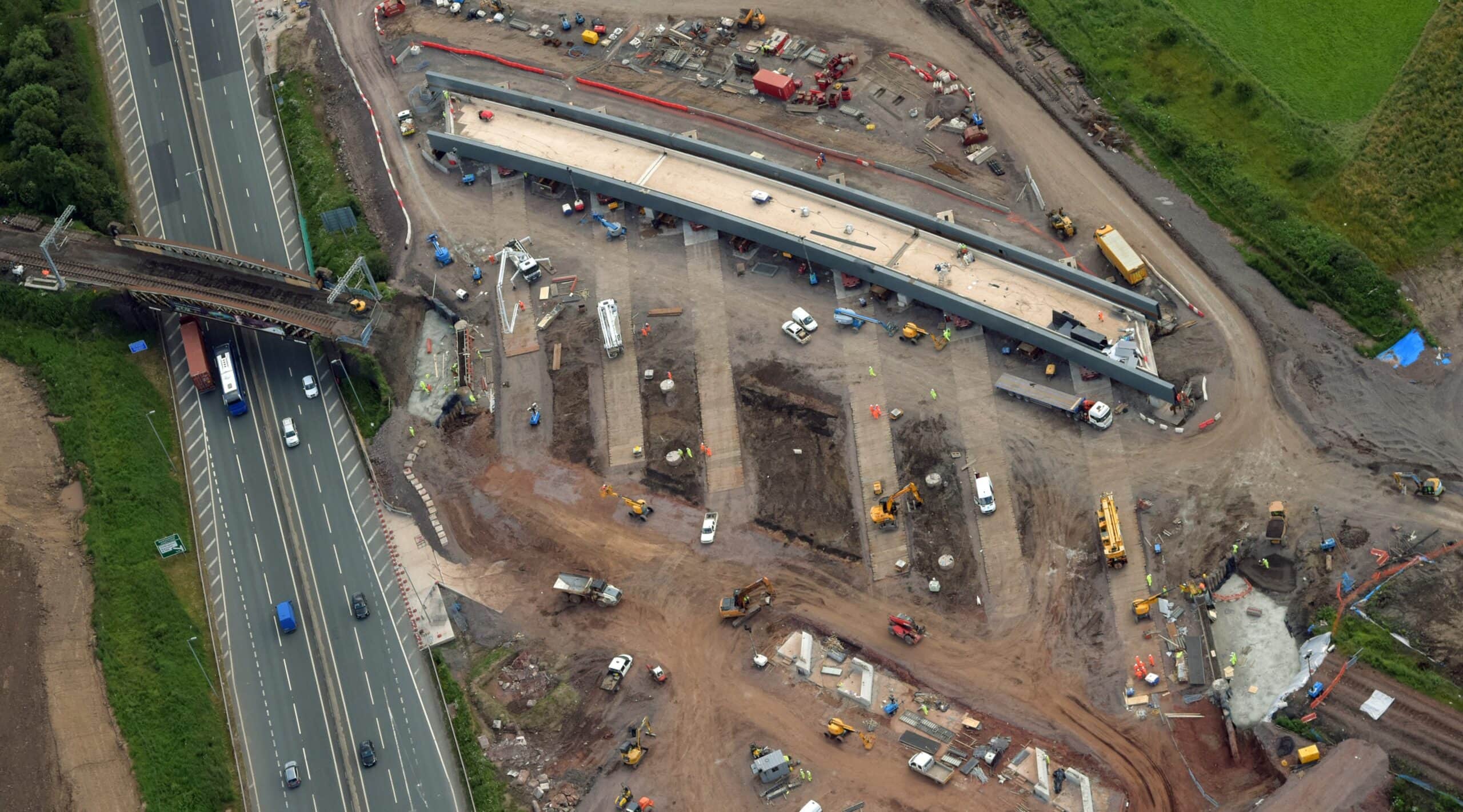
The deck has a main structure made up of two longitudinal structural steel girders with a trapezoidal box section (Main Girders), one on each side of the deck, with a total depth of 3.2 m, and a secondary transverse structure 0.9 m deep formed by a composite deck, set transversely to the main structure and resting on it, which carries the railway superstructure.
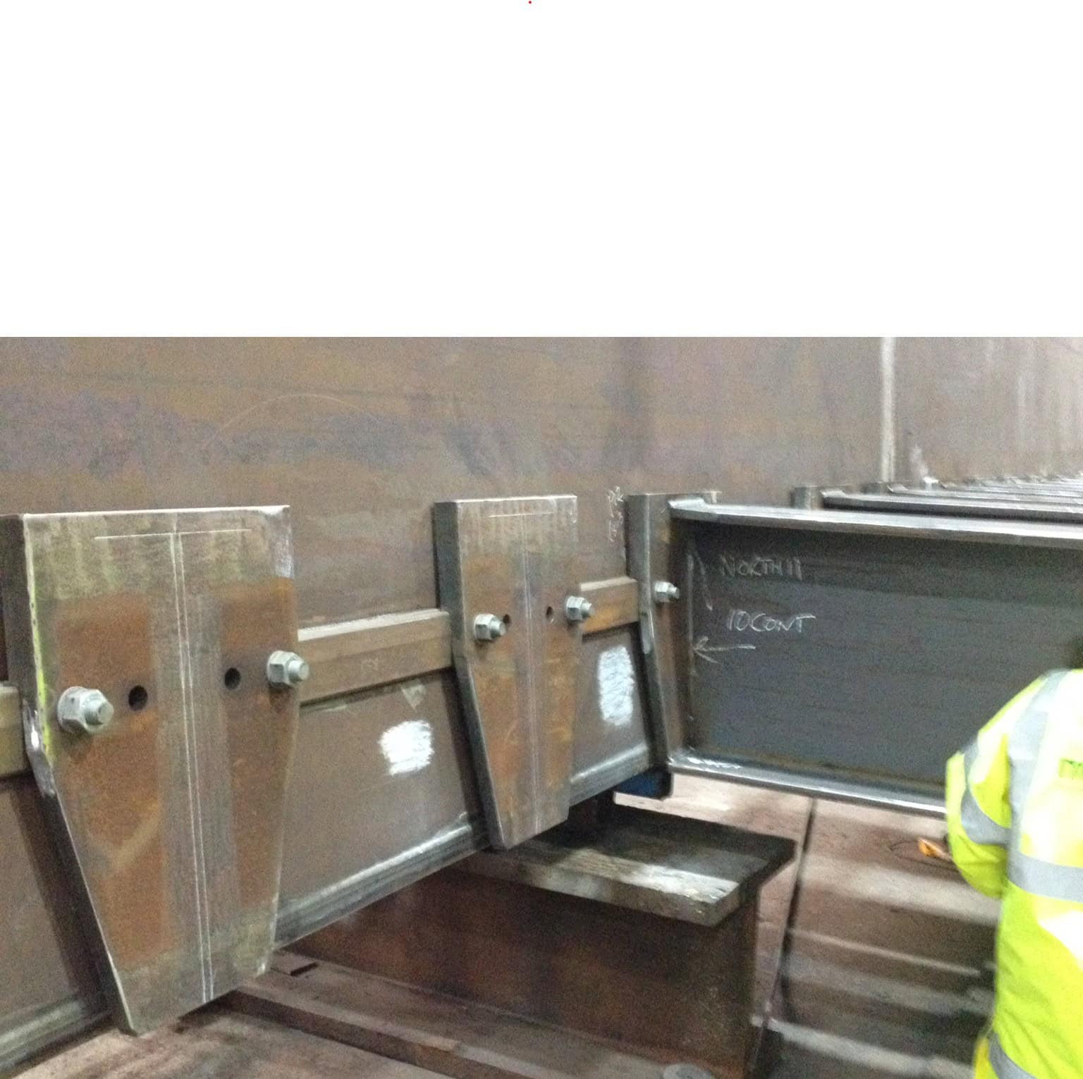
Between the longitudinal girders, and perpendicular to them, there are 0.62 m deep I-section cross beams (Floor Beams), evenly spaced every 0.95 m along the deck. On top of these beams, and connected to them, a reinforced concrete slab with an average thickness of 0.25 m completes the composite cross-section. These beams are connected to the main girders by pinned joints made with preloaded bolted connections.
Between the main girders, under the slab, there are nine closed-section cross beams (Trimmer Beams) along the deck, fixed at both ends to the main girders: one at each abutment (aligned with the bearing axes) and seven more, perpendicular to the bridge axis, at midspan (three) and at the piers (four).
Three structural steel elements are therefore defined:
Main Girders: located on both sides of the section, they are the main longitudinal structural elements and transfer the deck loads to the substructure.
Floor Beams: transverse structural elements located between the Main Girders. They are joined to them by pinned connections formed by rows of preloaded bolts and therefore work as simply supported beams spanning approximately 10.0 m. They transfer loads from the slab, which is connected to them, to the Main Girders, acting as secondary structural elements.
Trimmer Beams: transverse structural elements that belong to the main longitudinal structure. They have a closed box section 0.5 m deep and are fixed at both ends to the Main Girders to restrain their torsional rotation.
It is worth noting that the longitudinal girders of the bridge can be entered for inspection. Access doors were provided at their ends and at midspan, and it was ensured that an injured worker could be evacuated on a stretcher through the longitudinal and transverse stiffening system of the box and the pier and abutment diaphragms, in accordance with Network Rail safety standards.
The materials used were S355J2+N structural steel and C40/50 concrete.
Each pier and abutment consists of two 2.0 m diameter reinforced concrete pile-columns, socketed 6.0 m into the underlying bedrock, each supporting one longitudinal girder of the deck.
At the abutments, between the two pile-columns and extending beyond them as wing walls, a wall of 0.6 m diameter mini-piles is built, topped by a reinforced concrete capping beam. On top of the wall, between the pile-columns, a third deck bearing is placed on the longitudinal axis of the bridge. This central bearing limits the vertical movements of the deck at the abutment joint as trains pass, to levels acceptable in terms of track–deck interaction.
Behind the abutments there is a small plain-concrete transition wedge, topped by a reinforced concrete slab extending the deck slab but independent of it, which carries the railway superstructure. Each abutment was completed with two staircase structures for maintenance access, extending the ends of the longitudinal girders of the bridge.
The design of the piers and abutments was strongly influenced by the complex construction process of the bridge, defined so that it could be built with hardly any disruption to rail traffic beyond the possessions set by Network Rail, which totalled just over three weeks, split into 4 possessions of 54 h and a final 14-day possession.
The fixed point of the deck against longitudinal forces is at the piers.