
Project description
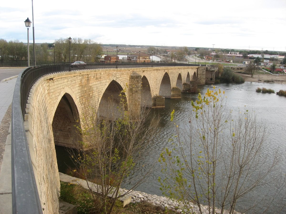
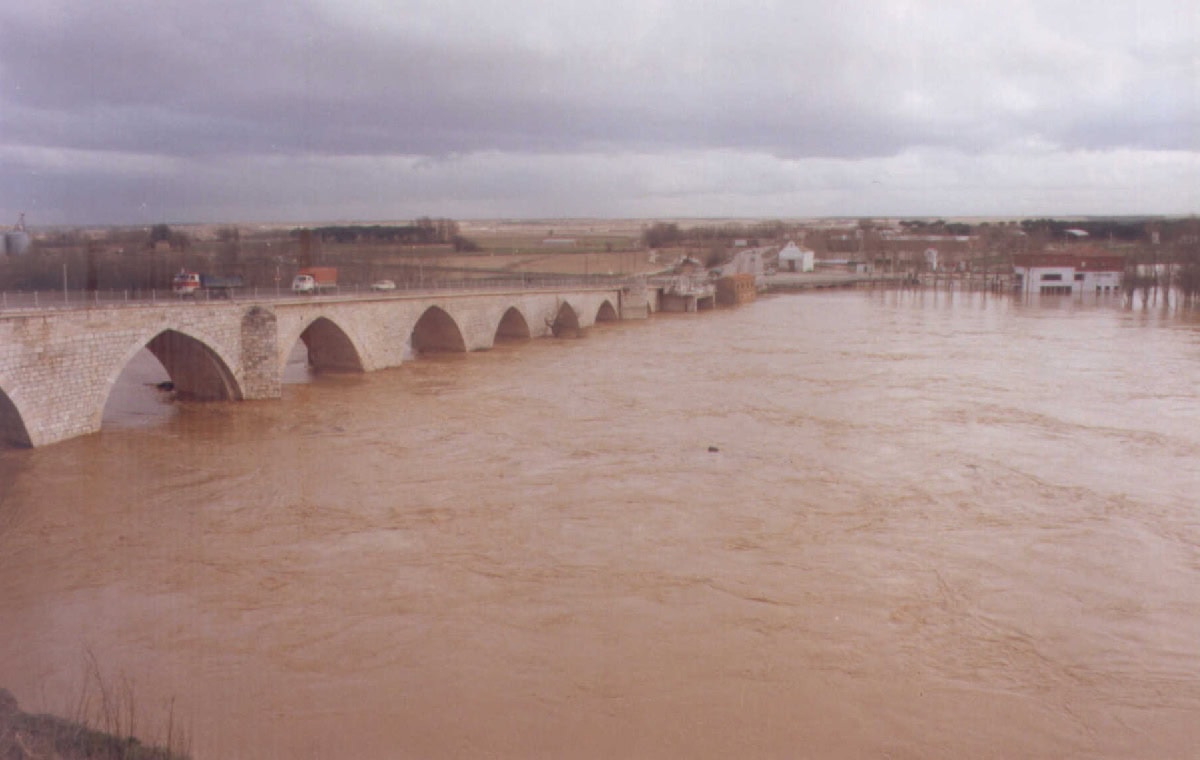
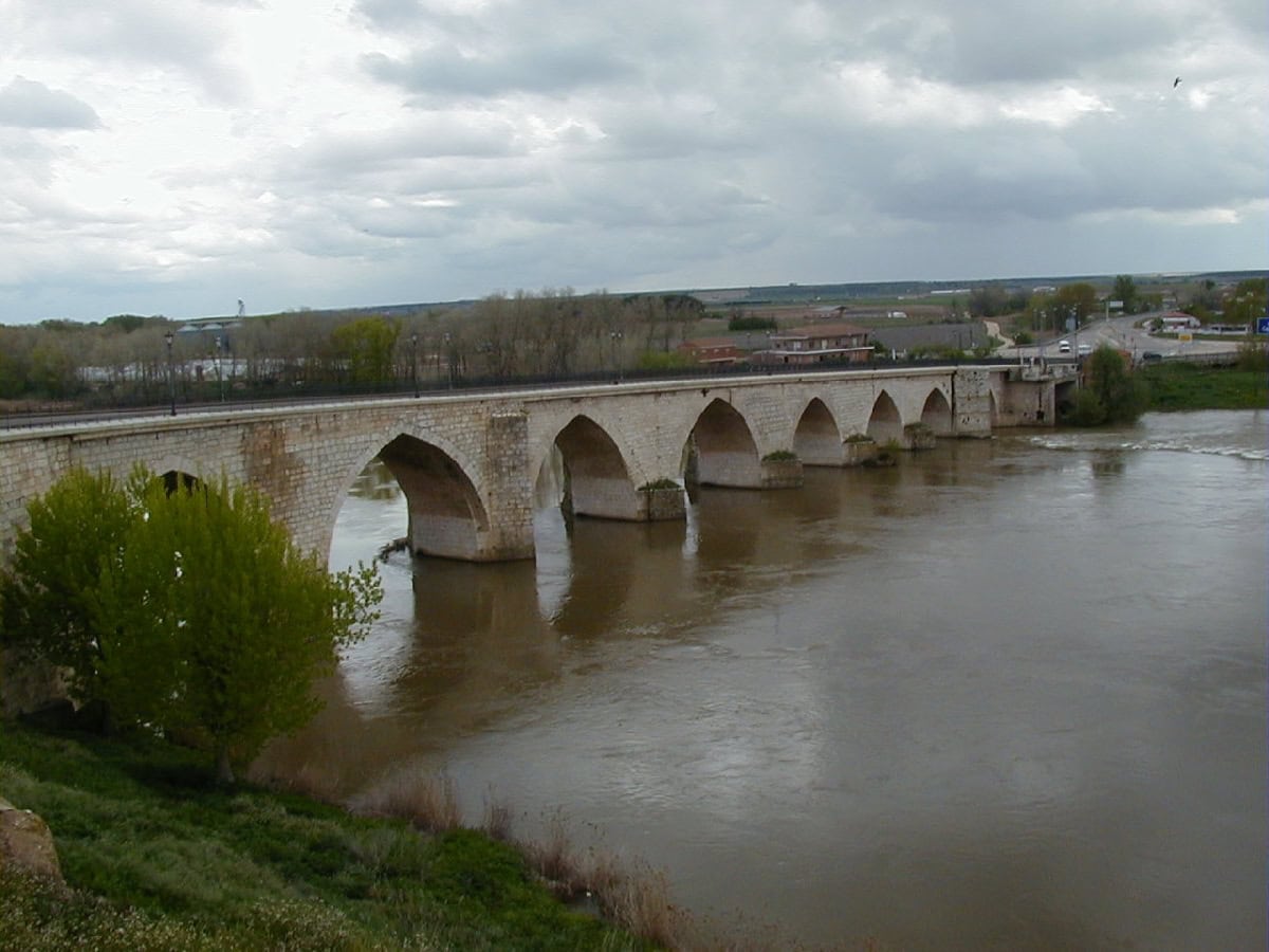
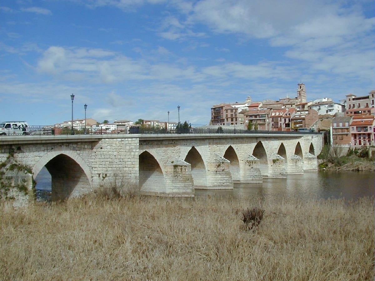
The Tordesillas bridge over the River Duero dates from around the middle of the 13th century and is located at km 181+500 of the N-VIa road, in the municipality of Tordesillas, province of Valladolid.
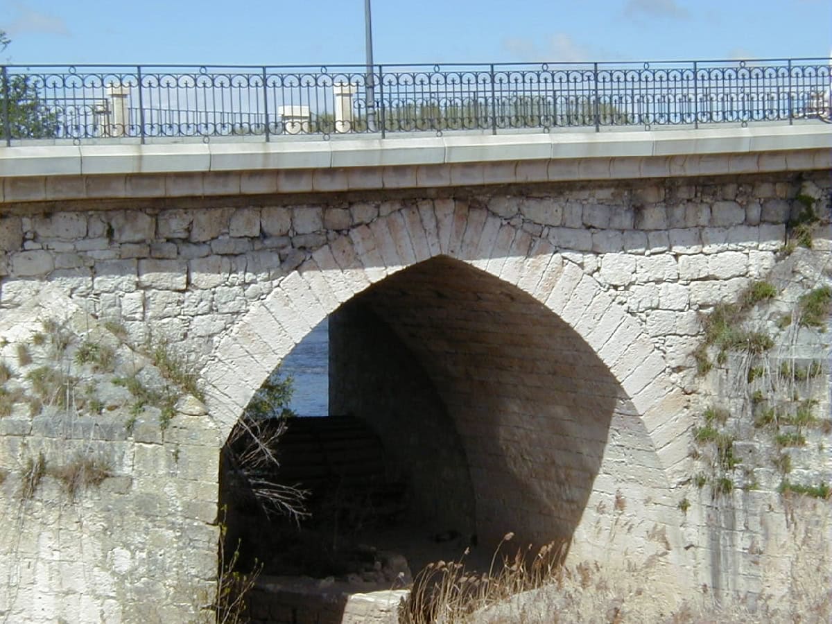
It is a medieval bridge of limestone ashlar masonry with ten pointed arches spanning between 9.5 and 16.3 m, with varying rise. Its total length is 182 metres between abutments, or 257 metres including the wing walls. The bridge has massive cutwaters and is 7.25 m wide in its ashlar masonry, plus a widening over the last two spans that varies from 1 m at pier 8 to 6.9 m at the La Coruña abutment.
The damage observed did not seem to indicate load-bearing problems in the medium term, except for the walkway and the viewpoint. However, the heritage value of this bridge meant that its current state of conservation had to be rated very poorly, as it is affected by progressive deterioration that could indeed cause structural problems if its causes are not addressed in time. Water seeping through the deck, the lack of adequate drainage, the inappropriate application of the deck loads on the masonry and birds nesting in existing cavities are the main causes of this deterioration.
To resolve the situation it seemed essential to dismantle the structure supporting the current deck and replace it with a new one, which had to keep at least the current width, distribute the loads correctly on the vaults and include adequate waterproofing and drainage. This radical intervention was also to be used to try to restore the bridge’s appearance, giving it a parapet and edge elements more suitable than the railing and cornices that replaced the original masonry parapet some forty years ago.
It was of course important that the rehabilitation should not increase the permanent loads. This was achieved in the final design by replacing the existing road surface and cantilevers with a reinforced concrete slab.
The opportunity was also taken to relieve the vaults of much of the stress caused by live loads, and especially of their harmful dynamic effects. The solution was to use the thickness of the road surface to place a continuous reinforced slab which, being stiffer, would carry the live-load stresses and transfer them to the sections over the piers. To prevent creep and shrinkage of the new deck concrete from harming the substructure, expansion joints were placed at piers 3, 6 and 8.
With the final design and the planned rehabilitation, the load-bearing capacity of the bridge will exceed both its original condition and that resulting from the widening.