
SARAMO VIADUCT (A CORUÑA)
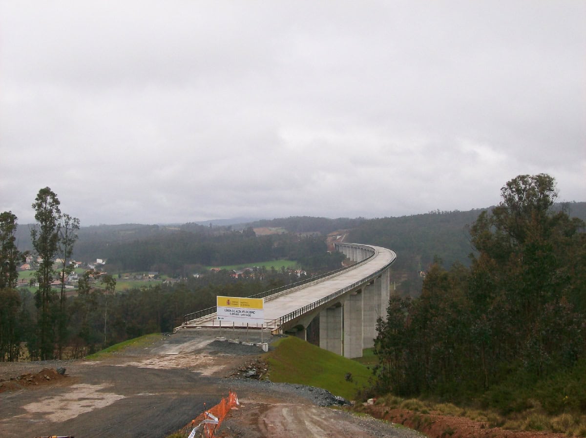
- Location: North-North Western segment of High Speed Railway (A Coruña) SEE MAP
- Scope of works: Construction project
- Structural type: Continuous box girder with constant depth.
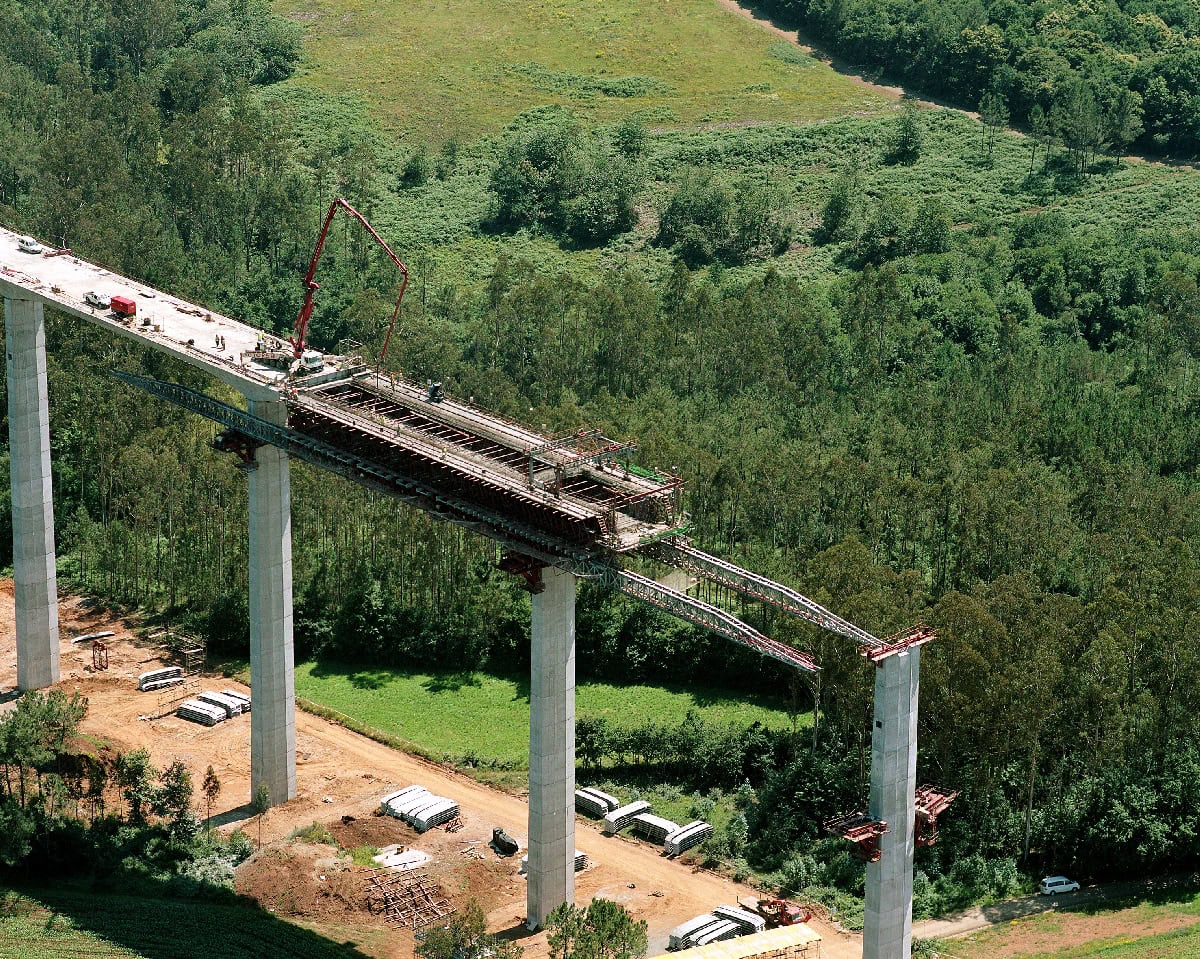
- Construction process: Self-launched formwork
- Overall length: 1485,0 m
- Spans: 46,40+24×58,0+46,40 m
- Deck width: 14,0 m
- Deck máximum height: 75,0 m
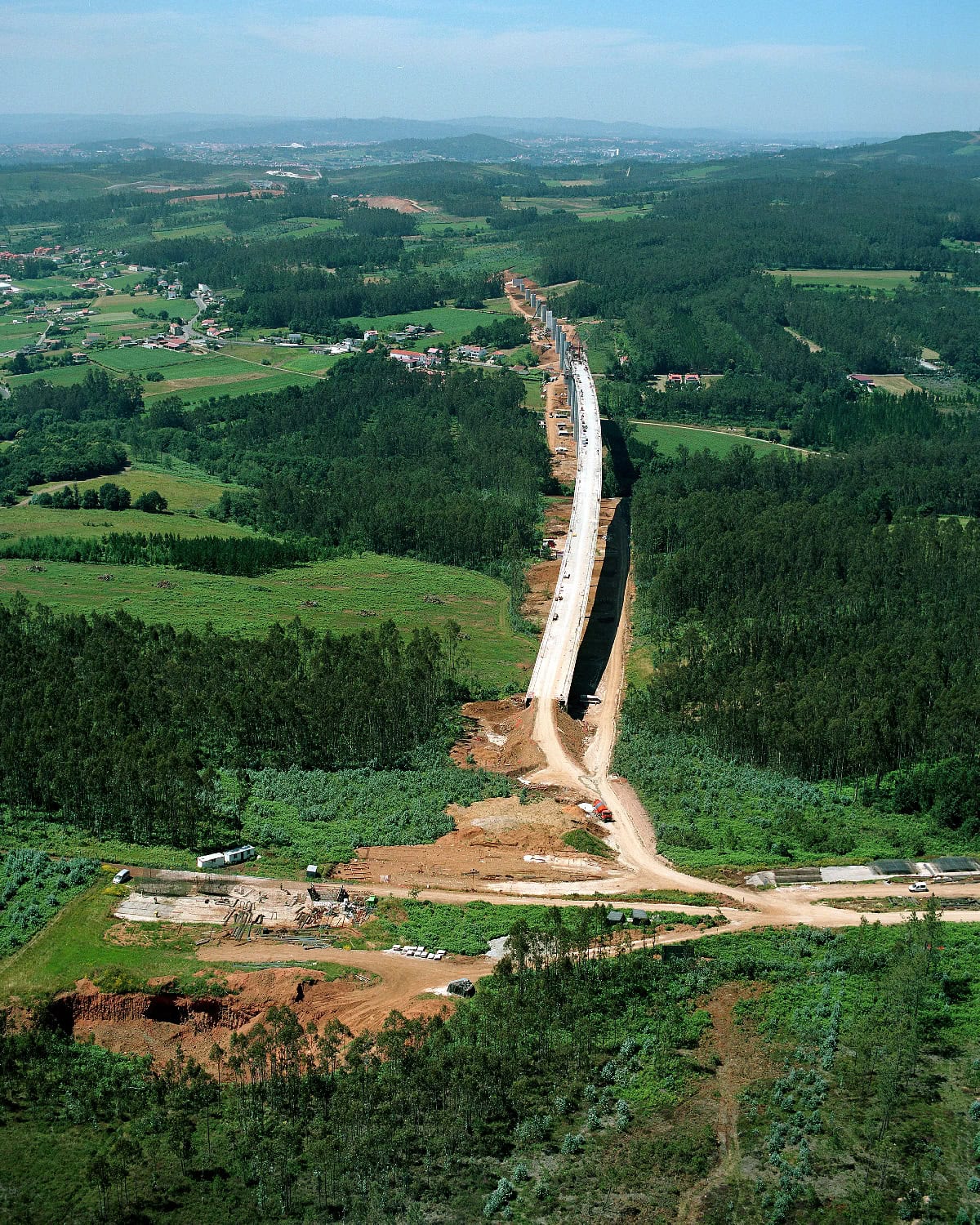
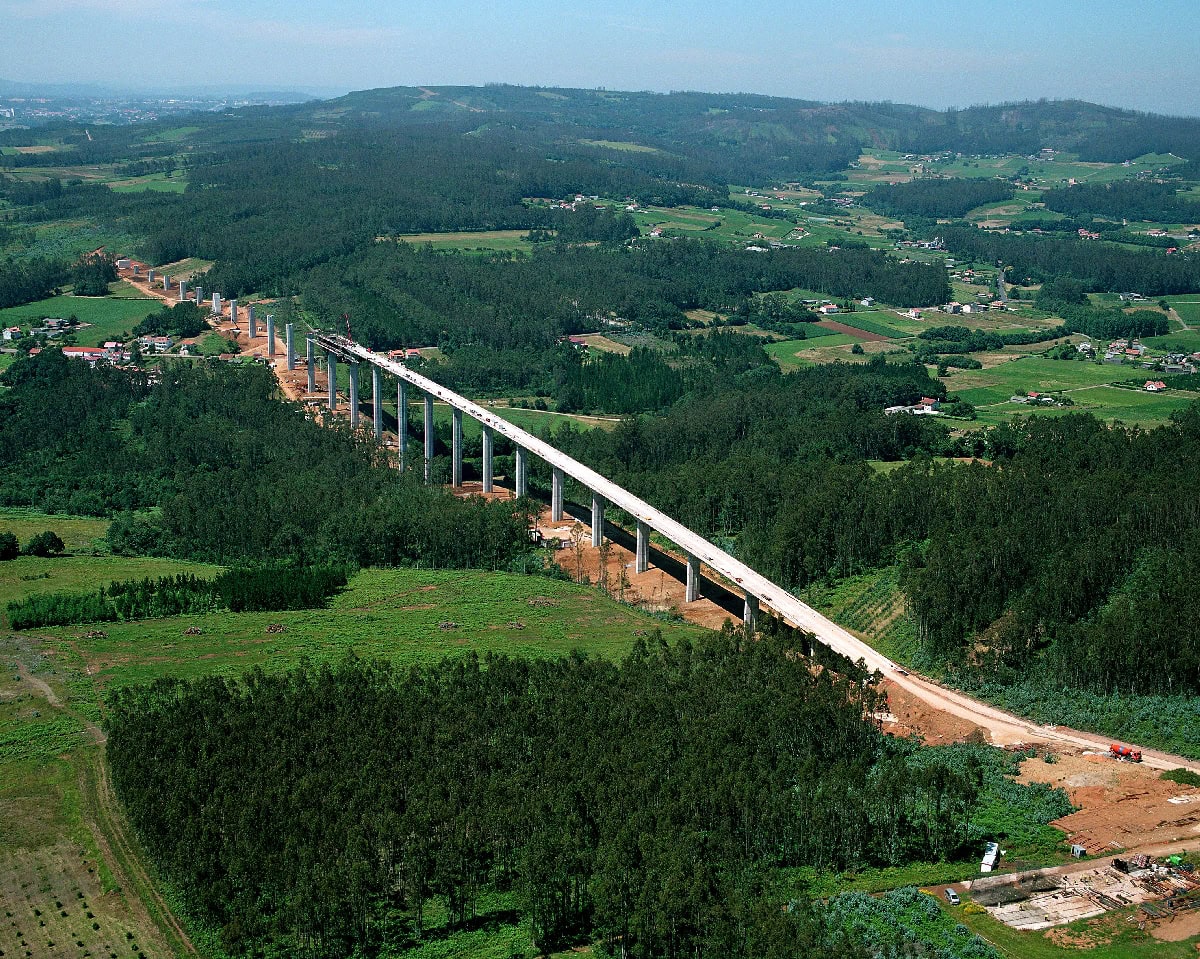
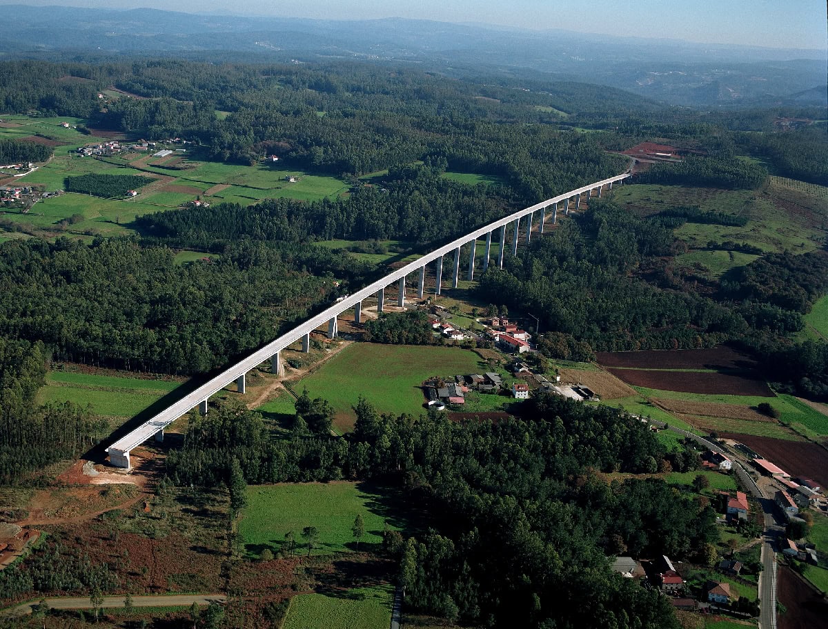
The new High Speed Railway line from Orense to Santiago, on the Vedra-Boqueixón section, passes over the Saramo River valley, which has a maximum height of seventy meters.
The overall length of the viaduct is 1485 m. The plan layout is a circular curve of 6000 m radius, and the longitudinal slope is 0.74%. The deck is made up of 26 spans with a span length distribution of 46,40+24×58,0+46,40 m. The positioning of the structure fulfils the environmental requirements imposed, including those of the riverbanks as well as the road and the “Hórreo de Sergude”, which is a catalogued monument.
The point of fixity of the deck is located at pier 20, which is a triangular “A” shaped cell in which the deck is embedded. The viaduct has expansion joints in both abutments.
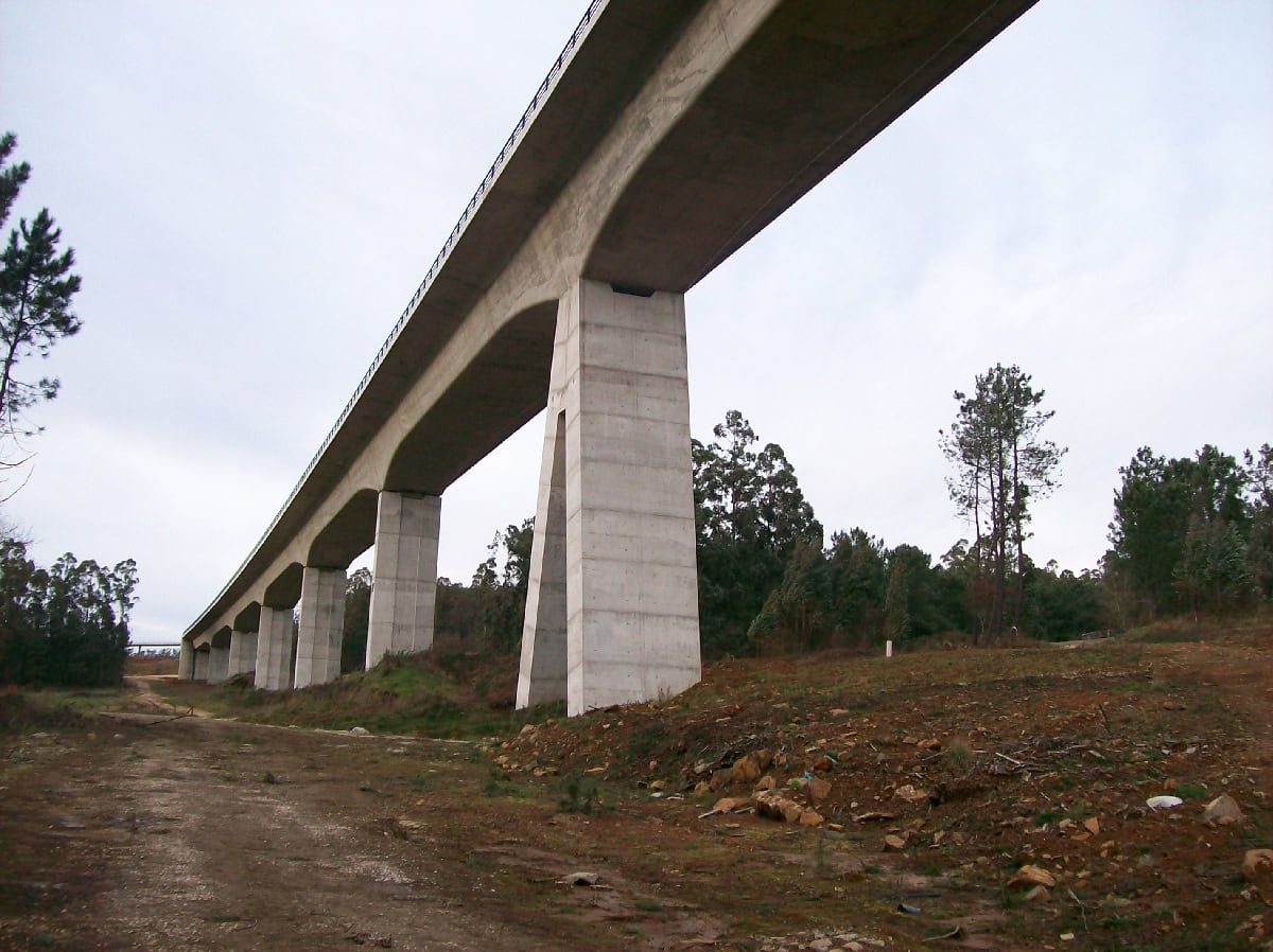
The deck is a continuous post-tensioned concrete box girder, with variable depth between 4.85 m and 3.25 m. The central portion of each deck, 34.8 m long, has constant depth. The cross section is a single-cell box with inclined webs, the bottom width varies from 5.50 m to 6.56 m, and the top width is constant at 8.50 m wide. There are also two lateral overhangs 2.75 m wide, which gives an overall width of 14.0 m.
The main deck prestressing system consists of tendons made of 37 strands located inside the box girder webs.
The cross sections of all the piers of the viaduct (except for pier 20) are hollow octagons. They have 0.30 m thick walls a constant width of 5.50 m and a variable depth with a minimum of 2.30 m at the top of the pier. The heights of the piers range from 11.3 m to 69.6 m.
Pier 20 is particular because it is the point of fixity of the deck. It is an “A” shape, consisting of two box girder struts of 2.30×5.50 m. The struts converge and are embedded in the deck. The footing of the pier is hollow, containing earth fill, which ensures its stability. The two struts of the pier are pre-stressed and anchored both in the deck and in the footing.
The viaduct abutments are conventional and made of reinforced concrete. They consist of a stem wall and lateral wingwalls. The initial abutment is the point of fixity of the deck during the construction stages.
The deck is supported by the piers by means of pairs of “POT” sliding bearings, one of the bearings is free and the other one unidirectional.
The deck was built using a self-launching formwork device.